Adding WiFi Ultrasonic Water Level Controller to CIP Tanks
Adding a level controller to a CIP tank is usually a retrofit, not a new build. The tank is already there, the CIP sequence already runs, and the buyer wants to add a trustworthy level reading without draining the tank or breaking the production schedule. This guide is the retrofit playbook: how to add a WiFi ultrasonic water level controller to an existing CIP tank, step by step, and what to watch for.
A CIP tank cycles through caustic, acid and rinse water, gets hosed down, and feeds a cleaning sequence that depends on a trustworthy level. A float switch in that chemistry jams; a contact probe drifts. An ultrasonic level controller takes the opposite route: the ultrasonic level sensor sits on top, reads the surface from the air, and never touches the product. The water level controller keeps level monitoring stable cycle after cycle. Adding one to an existing CIP tank is a top-mount retrofit, not a tank entry.
Step 1: Pick the mounting point
Look down into the tank from the top. Choose a nozzle or a bracket position over open liquid, clear of the inlet splash, the vent, and any internal baffle or dip pipe. The ultrasonic level sensor needs a clear acoustic path to the surface. A level controller aimed at an internal fitting returns a phantom level. On a CIP tank, the mounting point is the whole install, so choose it carefully.
Step 2: Respect the blind zone
The level sensor cannot read the closest 0.3 m below the transducer face. Leave that clearance above the maximum fill, so the water never sits inside the blind zone when the tank is full. If the CIP tank is shallow, mount the water level controller on a standoff or bracket that gives the headroom. A level controller mounted too close to the water goes blind at exactly the moment the overflow alarm matters.
Step 3: Wire the power and the relays
The level controller runs on 12–24 V DC. Tap the existing control supply at the CIP panel, and run a relay pair to the CIP supply or return pump. Set the pump-on and off levels with hysteresis, the dry-run lockout below the pump suction, and the overflow alarm at the high level. The relays run locally, so the pump protection works even if the WiFi drops. The water level controller's install is power in, relay out, and the level monitoring starts.
Step 4: Connect the WiFi
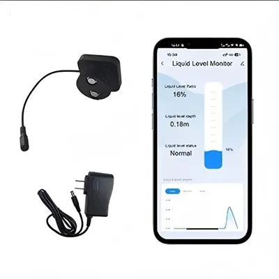
The level controller uses 2.4 GHz WiFi, IEEE 802.11 b/g/n. Survey the signal from the tank mounting point to the nearest access point. A stainless wall or steel structure attenuates it; place the water level sensor where the radio can see the AP, or add a repeater. The cloud dashboard and the app alarms are the remote layer; the local relay protection is the safety layer. Confirm the dashboard shows the CIP tank level before you leave the site.
Step 5: Handle the CIP conditions
CIP tanks add two conditions the installer must address. The first is foam: caustic and surfactant cycles can foam, and a thick foam layer fools the ultrasonic level sensor. Mount the level controller away from the most vigorous splashing, and tell the CIP operator to watch the first weeks. The second is hot rinse vapour: a hot cycle releases warm mist toward the transducer. Mount the water level controller off the vent path so condensation runs off the face, not over it. Neither condition rules out the level sensor, but both need a sensible mounting plan.
A worked retrofit
A 2.4 m CIP make-up tank, 50 °C caustic and rinse, CIP supply pump, hosed-down room. The installer mounts the ultrasonic level controller on the top nozzle over open liquid, clear of the inlet and the vent, on a standoff that gives 0.4 m clearance above the high level. Set supply pump-on at 30% and off at 85%, dry-run lockout at 12%, overflow alarm at 96%. The app alerts the CIP operator if the level lags, and the cloud history shows solution usage per batch. The retrofit took an afternoon, no tank drain, and the old float stays as a backup.
Before you walk away
Cross-check the reading against a sight glass, test the dry-run lockout by lowering the water, and confirm the overflow alarm fires. Leave the operator a one-page sheet: the setpoints, the relay wiring, and the contact for support. Send us your CIP tank dimensions and we will confirm the level sensor configuration before you add the unit.
A note on the first cycle
After the level controller is mounted, run one full CIP cycle through it. Watch the ultrasonic level sensor track the surface through caustic, acid rinse and clean water, and confirm the CIP supply pump setpoints and the dry-run lockout trip correctly. Leave the operator a one-page sheet with the setpoints and the relay wiring. A water level controller that has run through one real cycle on site is one the CIP team trusts. That first cycle is the commissioning that turns the retrofit into a working level monitoring system.
What the operator sees
The payoff of the retrofit is the operator's day. When they open the dashboard, they see the CIP tank level instead of a blind sequence, and the app tells them before the level lags. That visible level monitoring is what turns a retrofit into a daily tool. A water level controller the operator checks on a phone every shift is one that earns the spend, and the ultrasonic level sensor's stable reading means the team stops guessing whether the level held through the night.

Request the datasheet
Tell us the CIP tank height, chemistry and pump rating and we will recommend the ultrasonic water level controller, send the spec sheet with an RFQ, and offer a sample level controller to bench-test on your vessel. OEM and private-label configurations available.