High-Pressure Level Switch
A complete guide to high-pressure level switches: what "high pressure" means for level sensing (vessel pressure as the hostile element - seal extrusion, wetted-material attack, density change, and the danger of any leak), the pressure barrier problem (the sensing element sees process pressure; the electronics must not - and every technology is really a story about sealing), the technology menu under pressure (vibrating fork, RF admittance/capacitive, conductive probe, displacer, hydrostatic/differential pressure, guided wave radar, and the rare high-pressure optical), the key specifications (working vs proof vs burst pressure, temperature derating, wetted materials, process connections from NPT to ANSI 2500 flange, certification), the applications (hydraulic accumulators, compressor KO drums, steam drums, oil & gas separators, CO2 and ammonia systems, LPG/propane tanks, CNG storage), the selection funnel, installation and maintenance practices (isolation valves, bleed/drain, seal inspection), the FAQ, and the bottom line.
High-Pressure Level Switch - Quick Answer
A high-pressure level switch is a point-level sensor engineered for pressurized vessels - typically working pressures from roughly 500 psi (34 bar) up to 5,000+ psi (345+ bar) - where the vessel pressure itself is the hostile element: it tries to extrude seals, attack wetted materials, change the liquid's density, and turn any leak into a high-velocity, dangerous jet. The engineering is not about the sensing principle - it is about the pressure barrier: the sensing element must see process pressure, while the electronics must not, and every high-pressure level switch is ultimately a story about how that barrier is sealed (O-ring, metal seal, diaphragm isolation, ceramic-to-metal or glass-to-metal joints). The technology menu under pressure narrows fast: vibrating forks with pressure-rated bodies, RF admittance and capacitive probes (pressure-insensitive sensing, seal-limited), conductive probes, displacers, hydrostatic/differential pressure for pressurized vessels (where level is computed from the pressure difference), guided wave radar for continuous high-pressure duty, and - rarely - optical switches with pressure-rated windows. The selection funnel is: media → pressure class (working/proof/burst) → temperature (the derating curve) → wetted materials → process connection (NPT to ANSI flange) → output → certification (ASME/PED/CRN, ATEX). The golden rule: never buy on the working-pressure number alone - check the temperature-derated rating, the wetted-material compatibility, and the seal design, because at high pressure, the seal is the sensor. (The automation context: Level Switches for Tanks for Automation; the full family: Guide to Liquid Level Sensors.)
What "High Pressure" Does to Level Sensing
The Four Hostile Effects
The pressure effects:
| Effect | What happens | Why it matters |
|---|---|---|
| Seal extrusion | Pressure pushes seals into gaps | Leak path, sensor failure |
| Density change | Liquid compresses under pressure | Float buoyancy shifts |
| Gas headspace | Gas density rises sharply | Floats/fork behavior changes |
| Jet hazard | Any leak becomes high-velocity | Danger to people and equipment |
Pressure attacks the sensor through four channels at once: High pressure is not just a number on a datasheet - it is an environment that attacks the sensor through four channels simultaneously. Seal extrusion: pressure forces elastomer seals into microscopic gaps, creating leak paths and destroying the seal; this is why high-pressure designs use backup rings, metal seals, or welded/diaphragm isolation instead of a plain O-ring. Density change: liquids compress under pressure - at 5,000 psi, many liquids are several percent denser - which shifts the buoyancy that float and displacer switches depend on, so their set points move. Gas headspace: the gas above the liquid becomes dramatically denser under pressure, changing how floats, forks, and ultrasonic elements behave in the vapor space. And the jet hazard: any leak at high pressure is a high-velocity jet - cutting, spraying, and dangerous - which is why the process connection and seal quality are safety matters, not convenience matters. A high-pressure level switch must survive all four effects, which is why it is a different product from its atmospheric cousin, not just a stronger version. (The same physics discipline, sensor-wide: Sensor Data Sheet: How to Read and Use One.)
The Pressure Barrier Problem
The Sensing Element Sees Pressure; the Electronics Must Not
The barrier designs:
| Barrier | How it works | Where used |
|---|---|---|
| O-ring + backup ring | Elastomer seal, anti-extrusion ring | Moderate pressure |
| Metal seal | C-ring, lens ring, metal-to-metal | High pressure, high temp |
| Diaphragm isolation | Thin diaphragm transmits pressure | Process isolation |
| Ceramic/metal joint | Brazed or welded joint | Sensor elements |
| Glass-to-metal seal | Hermetic electrical feedthrough | Electrical exit |
Every high-pressure switch is a barrier design wearing different clothes: The core engineering problem in a high-pressure level switch is the barrier: the sensing element must contact the process, the electronics must not, and the boundary between them must hold the vessel pressure - and the process chemistry - for the life of the device. The barrier designs form a ladder. O-rings with anti-extrusion backup rings serve moderate pressures and temperatures. Metal seals - C-rings, lens rings, metal-to-metal contacts - take over at high pressure and high temperature where elastomers fail. Diaphragm isolation puts a thin metal or ceramic diaphragm between process and sensor, transmitting pressure while protecting the element. Ceramic-to-metal brazed joints seal the sensing elements themselves, and glass-to-metal seals bring the electrical wires out hermetically. The practical lesson: when you open a high-pressure level switch's datasheet, look for what seals the process side - an O-ring-only design is a low-pressure design wearing a high-pressure label; a metal-seal or diaphragm-isolated design is the real thing. The barrier is the sensor. (The same "look at the actual engineering" discipline: What Is a Liquid Level Sensor?)
The Technology Menu Under Pressure
What Survives, and What Does Not
The technologies:
| Technology | High-pressure capability | Notes |
|---|---|---|
| Vibrating fork | Good (pressure-rated bodies) | Solid-state, general purpose |
| RF admittance/capacitive | Excellent (seal-limited) | Coating-tolerant, interface |
| Conductive probe | Good (insulator-rated) | Water-based media only |
| Displacer/float | Fair (buoyancy shifts) | Density-compensated designs |
| Hydrostatic/diff pressure | Excellent | Level from pressure difference |
| Guided wave radar | Excellent (continuous) | Hundreds of bar capability |
| Optical TIR | Rare (pressure window) | Clean liquids, niche |
Pressure is a filter that eliminates most of the menu: The technology menu for level sensing collapses under pressure, and what survives is instructive. Vibrating forks with pressure-rated bodies handle high-pressure liquids and slurries - solid-state, no seals in the sensing path beyond the process connection. RF admittance and capacitive probes are inherently pressure-insensitive - the measurement is dielectric, not mechanical - so their limit is the seal and insulator, which well-made versions push very high. Conductive probes work if the insulator is pressure-rated and the media is conductive (water-based). Displacers and floats get complicated: buoyancy shifts with density, so high-pressure service needs density-compensated designs and careful set-point verification. Hydrostatic and differential pressure are the classic pressurized-vessel answer: measure the pressure difference between the bottom and the top (or atmosphere), and the level follows - this is how steam drums and separators are gauged. Guided wave radar does continuous level at hundreds of bar - the workhorse of high-pressure continuous duty. Optical TIR switches are rare under high pressure because they need a pressure-rated window, though sapphire-window versions exist for niche clean-liquid duties. The rule: mechanical principles (float) suffer most; electrical principles (capacitive, conductive) suffer least; and if you need continuous level at high pressure, differential pressure or guided wave radar owns the job. (The point-versus-continuous frame that decides switch vs transmitter: Point vs Continuous Level Sensing.)
The Key Specifications
Working, Proof, Burst - and the Derating Curve
The spec set:
| Spec | Meaning | Why it matters |
|---|---|---|
| Working pressure | Continuous max | The operating number |
| Proof pressure | One-time, no damage | Overpressure survival |
| Burst pressure | Catastrophic limit | Safety margin |
| Temperature derating | Rating drops as temp rises | The real rating |
| Wetted materials | What touches process | Corrosion survival |
| Connection rating | NPT, ANSI flange class | The weakest link check |
The working-pressure number is a headline; the derating curve is the truth: High-pressure level switch selection starts with understanding the spec hierarchy. Working pressure is the continuous maximum - the number on the front of the datasheet. Proof pressure is the one-time overpressure the device survives without damage. Burst pressure is the catastrophic limit - the margin between them is your safety factor. But the spec that actually decides fitness is the temperature derating curve: pressure ratings drop as temperature rises, because seal materials and metal strengths degrade - a switch rated 3,000 psi at 100 °F may be rated 1,500 psi at 400 °F, and the derating curve, not the headline, is what you must compare to your actual operating point. Wetted materials matter as much as pressure: at high pressure, corrosion is faster (higher stress, higher temperature), so 316 SS, Hastelloy, Inconel, and PTFE choices are survival decisions, not upgrades. And the connection rating is the final check: an ANSI 150 flange on a 3,000-psi switch is a leak waiting to happen - the process connection must be rated for the same class as the sensor. Four numbers and one curve: working, proof, burst, derated-at-temperature, plus the wetted materials and the connection. (The discipline of reading a datasheet properly: Sensor Data Sheet: How to Read and Use One.)
The Applications
Where High-Pressure Level Switches Earn Their Keep
The applications:
| Application | Pressure range | Switch role |
|---|---|---|
| Hydraulic accumulators | 1,000–6,000 psi | Low/high alarms, charge control |
| Compressor KO drums | 500–3,000 psi | Liquid carryover protection |
| Steam drums / boilers | 1,000–3,500 psi | Low-water cutoff, feed control |
| Oil & gas separators | 500–5,000+ psi | Interface and level control |
| CO2 / ammonia systems | 200–2,000 psi | High-level protection |
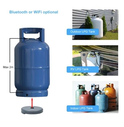
| LPG / propane tanks | 100–300 psi | High-level shutdown |
| CNG storage | 3,000–5,000 psi | Level (liquid) and pressure safety |
High-pressure switches protect the vessels that run the plant: The applications are the vessels where pressure is the defining condition. Hydraulic accumulators (1,000–6,000 psi) use level switches for charge control and low/high alarms - a bladder-less accumulator with wrong level is a safety event. Compressor knockout drums use switches to stop liquid carryover into the compressor - the classic "liquid in the suction kills the machine" protection. Steam drums and boilers (1,000–3,500 psi) use low-water cutoffs - the most safety-critical level switch application in industry; a boiler running dry is a catastrophic failure. Oil & gas separators (500–5,000+ psi) need interface and level control at pressures where the fluid is often at its bubble point. CO2 and ammonia refrigeration systems need high-level protection at moderate high pressures. LPG/propane tanks (100–300 psi) use high-level switches for overfill shutdown - the everyday version of this whole story. And CNG storage (3,000–5,000 psi) pushes the spec envelope entirely. In every case the pattern is the same: the switch is a safety or protection element whose failure mode is the dangerous one, which is why pressure rating, certification, and proof testing are not paperwork - they are the design. (The industry-wide view: Global Experts in Gas & Liquid Sensor Solutions.)
The Selection Funnel
Media → Pressure → Temperature → Materials → Connection → Output → Certification
The funnel:
| Step | Question | Eliminates |
|---|---|---|
| 1. Media | Liquid, slurry, interface, conductive? | Conductive (non-conductive), etc. |
| 2. Pressure class | Working, proof, burst, derated at temp | Whole product classes |
| 3. Temperature | Process temp + derating curve | Seal materials |
| 4. Wetted materials | Corrosion compatibility | Most standard bodies |
| 5. Connection | NPT, flange class, clamp | Fit options |
| 6. Output | Relay, PNP/NPN, Namur, 4–20 mA | Controller compatibility |
| 7. Certification | ASME/PED/CRN, ATEX, SIL | Non-certified versions |
Seven steps, and the first three do most of the work: The selection funnel for a high-pressure level switch is the standard funnel with pressure moved to the front. Media first - conductive, slurry, interface, clean liquid - because it eliminates technologies immediately. Pressure class second, and here is the discipline: compare working, proof, and burst, and derate by the actual process temperature, not the datasheet headline - this one step eliminates most of the market. Temperature third, because it drives the seal material and the derated rating together. Wetted materials fourth - corrosion compatibility at the actual pressure and temperature. Connection fifth - NPT for small lines, flanges for vessels (rating matched to the sensor class). Output sixth - relay, PNP/NPN, Namur, or 4–20 mA to match the controller. Certification seventh - ASME/PED/CRN for pressure vessels, ATEX/IECEx for hazardous areas, SIL for safety loops. The first three steps - media, pressure at temperature, materials - do the heavy elimination; the rest is matching. Follow the funnel and the shortlist is defensible; skip it and the "high-pressure" label on the datasheet does the selling instead of the engineering. (The same funnel logic as every sensor purchase: Guide to Liquid Level Sensors.)
Installation and Maintenance
Isolation, Bleed, Seals, and Proof Testing
The practices:
| Practice | Why |
|---|---|
| Isolation valve | Service without depressurizing the vessel |
| Bleed/drain before removal | Depressurize and drain safely |
| Seal inspection | O-rings and metal seals degrade |
| Torque to spec | Connection tightness is a pressure rating |
| Proof testing | Safety switches must be proven |
| Derating awareness | Operating near the curve invites failure |
At high pressure, installation discipline is a pressure rating: Installation and maintenance practices for high-pressure switches are safety practices first. Fit an isolation valve so the switch can be serviced without depressurizing the vessel - and remember the isolation valve itself must be rated for the full pressure. Bleed and drain the line before removing anything; a pressurized switch removal is a jet-in-the-face event. Inspect seals on schedule - O-rings harden and metal seals fret, and at high pressure a degraded seal is a leak path. Torque the process connection to specification - connection tightness is literally part of the pressure rating; under-torqued connections leak and over-torqued ones stress the body. Proof-test safety switches on schedule - the function must be proven, not assumed. And stay aware of the derating curve in operation: a process that drifts toward the derated limit is a process inviting failure. The switch itself may be simple; the discipline around it is what makes high-pressure service survivable. (The same installation rigor, automation-wide: Level Switches for Tanks for Automation.)
FAQ
Q1: What is considered a high-pressure level switch?
There is no universal line, but in practice "high pressure" level switches are engineered for roughly 500 psi (34 bar) and above, with industrial versions reaching 5,000+ psi (345+ bar). The label means the sensing element, seals, wetted materials, and process connection are all engineered for that pressure - not just the body casting.
Q2: Which level switch technology works best at high pressure?
RF admittance/capacitive probes are pressure-insensitive (their limit is the seal), conductive probes work for water-based media with pressure-rated insulators, vibrating forks have pressure-rated bodies for liquids and slurries, and guided wave radar or differential pressure are the standard choices for continuous high-pressure level. Float/displacer designs suffer from density shifts and need compensation.
Q3: Why does the temperature derating curve matter for high-pressure level switches?
Pressure ratings drop as temperature rises because seal materials and metal strengths degrade. A switch rated 3,000 psi at 100 °F may be rated far less at 400 °F. The derating curve, not the headline working-pressure number, is what you must compare to your actual operating point.
Q4: What is the difference between working, proof, and burst pressure?
Working pressure is the continuous maximum operating pressure. Proof pressure is the one-time overpressure the device survives without damage. Burst pressure is the catastrophic failure limit. The margin between them is your safety factor - always compare all three against your process and any overpressure scenarios.
Q5: Can I use a regular level switch on a high-pressure vessel?
Not safely. A regular switch's seals and wetted materials are not engineered for high pressure: O-rings extrude, connections leak, and a high-pressure leak is a dangerous jet. Use a switch rated for your pressure class at your process temperature, with wetted materials compatible with the media, a properly rated connection, and appropriate certification.
The Bottom Line
A high-pressure level switch is a point-level sensor engineered for pressurized vessels - typically 500 to 5,000+ psi - where the vessel pressure itself is the hostile element, attacking through seal extrusion, density change, gas-headspace effects, and the jet hazard of any leak. The engineering is not the sensing principle; it is the pressure barrier - the sensing element must see process pressure while the electronics must not, and every high-pressure switch is a story about that seal (O-ring with backup ring, metal seal, diaphragm isolation, ceramic-to-metal or glass-to-metal joints). The technology menu narrows under pressure: vibrating forks with pressure-rated bodies, RF admittance and capacitive probes (pressure-insensitive, seal-limited), conductive probes, compensated displacers, differential pressure for pressurized vessels, guided wave radar for continuous high-pressure duty, and rare optical switches with pressure-rated windows. Selection is a seven-step funnel with pressure moved to the front: media → pressure class (working, proof, burst, derated at actual temperature) → temperature → wetted materials → connection (rated to the same class) → output → certification (ASME/PED/CRN, ATEX, SIL). The golden rules: never buy on the working-pressure headline alone - check the temperature-derated rating, the wetted-material compatibility, and the seal design, because at high pressure the seal is the sensor; and install with the discipline that is itself a pressure rating - isolation valves, bleed/drain before removal, seal inspection, torque to spec, proof testing. The applications - hydraulic accumulators, compressor KO drums, steam drums, separators, CO2 and ammonia systems, LPG/propane tanks, CNG storage - are the vessels where pressure is the defining condition and the switch is the protection. High-pressure level switches are not stronger versions of low-pressure switches; they are different machines, built around one idea: the barrier holds, and the level is known. (The automation context: Level Switches for Tanks for Automation; the family: Guide to Liquid Level Sensors; the datasheet discipline: Sensor Data Sheet: How to Read and Use One.)
Last updated: August 2026
Disclaimer: This article is an educational overview of high-pressure level switches for industrial applications, for general reference. Pressure ranges cited (roughly 500–5,000+ psi / 34–345+ bar across applications), technology capabilities (vibrating fork, RF admittance, capacitive, conductive, displacer, differential pressure, guided wave radar, optical), specification concepts (working, proof, burst, temperature derating, wetted materials), standards referenced (ASME, PED, CRN, ATEX/IECEx, SIL), and selection practices reflect common industry knowledge and vary by manufacturer, model, and application; always confirm ratings, derating curves, materials, certifications, and installation with the manufacturer's documentation and applicable codes. High-pressure process and safety applications must be engineered by qualified professionals. This guide is not affiliated with any instrument manufacturer.