How Do Non-Mechanical Solid-State Optical Switches Work?
In this guide: How non-mechanical solid-state optical switches work - the internal components, the step-by-step signal chain from infrared LED to digital output, the optics (Snell's law and total internal reflection), and the complete FAQ explaining why "no moving parts" is the whole point.
How Do Non-Mechanical Solid-State Optical Switches Work: Quick Answer
Non-mechanical solid-state optical switches work by shining infrared light from an LED inside a sealed tip and letting the presence or absence of liquid change how that light behaves - when the tip is dry, light totally internally reflects back to a photodetector (empty signal); when liquid contacts the tip, the light refracts out and the detector sees a sharp drop (liquid-present signal). There is no float, arm, spring, magnet, or reed contact: the only "moving" thing is a photon. The photodetector's light level is compared to a fixed threshold by onboard electronics, which then drives a semiconductor output transistor (NPN or PNP) on or off - that transistor is the "solid-state switch," switching electrically with no mechanical contact to wear or stick. The whole chain is: LED emits → tip dry = reflect to detector → tip wet = refract away → detector level drops → comparator crosses threshold → output transistor switches → digital "liquid / no-liquid" signal. This guide walks through each stage, the optics behind it, and why the non-mechanical design is what makes optical switches reliable.
The Internal Components
What Is Actually Inside
A non-mechanical optical switch contains only solid, stationary parts - no moving element anywhere:
| Component | Function |
|---|---|
| Infrared LED | Emits light into the tip (typically ~850–950 nm) |
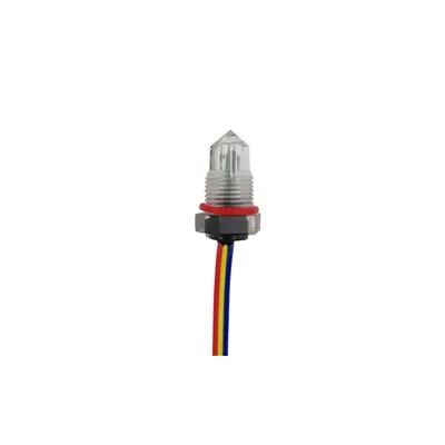
| Polished tip (prism) | Shapes the light path; the only part that touches liquid |
| Photodetector | Measures how much light returns (photodiode/phototransistor) |
| Comparator / ASIC | Compares detector level to a threshold |
| Output transistor | NPN or PNP semiconductor that switches the load |
| Sealed housing | Molded plastic or metal body; keeps electronics dry |
Nothing moves: Contrast this with a float switch, where a buoyant element, pivot, spring, and reed switch must all physically actuate. In an optical switch, the LED, detector, and transistor are fixed in place for the device's entire life. The "switching" is done entirely by semiconductor physics in the output transistor - which is why the device is called "solid state" and "non-mechanical."
The Step-by-Step Signal Chain
From Photon to Digital Output
Here is exactly how a level decision is made, stage by stage:
| Stage | What Happens | Electrical Result |
|---|---|---|
| 1. Emit | LED drives infrared light into the tip | Constant optical input |
| 2. Tip dry | Light totally internally reflects to detector | High returned light → high detector current |
| 3. Tip wet | Liquid contacts tip; light refracts out | Low returned light → low detector current |
| 4. Detect | Photodetector converts light to current/voltage | Analog level rises (dry) or falls (wet) |
| 5. Compare | Comparator checks level vs. fixed threshold | Crosses threshold at the wet/dry transition |
| 6. Switch | Output transistor turns on or off | Digital NPN/PNP signal flips |
| 7. Output | Load (PLC, pump, alarm) reads state | "Liquid present" or "Empty" |
The threshold is the decision point: The comparator is set so that the strong return-light current of a dry tip reads as one logic state and the weak return of a wet tip reads as the other. Because the dry-vs-wet contrast is large (most light returns when dry; much escapes when wet), the threshold crossing is decisive and hysteresis can be added to ignore momentary wave contacts - which is how optical switches resist sloshing false-trips.
The Optics: Snell's Law and Total Internal Reflection
Why Dry Reflects and Wet Refracts
The detection is pure geometric optics at a refractive-index boundary:
| Condition | Refractive Indices | What Happens at the Tip Surface | Detector |
|---|---|---|---|
| Dry (air) | Tip ≈ 1.5 → Air 1.0 | Light goes higher→lower index at shallow angle → total internal reflection (TIR) | Strong return (high) |
| Wet (liquid) | Tip ≈ 1.5 → Liquid ≈ 1.33 | Smaller index drop; TIR fails at that angle → refraction out | Weak return (low) |
The critical angle: Total internal reflection occurs only when light travels from a higher-index medium to a lower-index one and the incidence angle exceeds the critical angle θ_c = arcsin(n_low / n_high). Dry, the tip-to-air step (1.5 → 1.0) easily satisfies TIR, so light bounces back to the detector. Wet, the tip-to-liquid step (1.5 → 1.33) is a much smaller drop; at the same geometry, TIR fails and a large fraction of the light escapes into the liquid. The detector's job is simply to notice that the returned light got much weaker - and the electronics turn that into a switch decision. Opacity of the liquid does not matter; the light never passes through the bulk liquid, only interacts at the tip surface.
Why "Non-Mechanical" Matters
The Reliability Consequence
The non-mechanical design is not a curiosity - it is the source of every reliability advantage:
| Failure Mode (Mechanical Float) | Present in Optical Switch? | Reason |
|---|---|---|
| Float sticks from coating | No | No float to stick |
| Pivot arm wears / fatigues | No | No pivot |
| Reed contact oxidizes / bounces | No | No contact; semiconductor switch |
| Magnet weakens | No | No magnet |
| Travel-time delay | No | Photon speed; ms response |
| Mechanical fatigue over cycles | No | No moving part to fatigue |
The semiconductor switch: The output transistor (NPN sinks current, PNP sources current) is a solid-state device with no contacts to arc, bounce, or oxidize. It can switch millions of times without wear - the "switch" in "optical level switch" refers to this transistor, not to any mechanical action. That is the precise meaning of "non-mechanical solid-state": the level decision and the electrical switching are both performed by light and semiconductors, with zero mechanical motion anywhere in the signal path.
Output Types and Electronics
How the Switch Talks to Your System
The final stage offers standard industrial and logic-friendly outputs:
| Output Type | Behavior | Common Use |
|---|---|---|
| NPN (sinking) | Transistor pulls load to ground when active | PLCs (sinking inputs), 12/24 V |
| PNP (sourcing) | Transistor supplies voltage when active | PLCs (sourcing inputs), 12/24 V |
| Normally Open (NO) | Output on when liquid detected | Alarm on fill |
| Normally Closed (NC) | Output on when dry | Pump-run / dry alarm |
| 5 V logic | Direct to microcontroller | Battery / portable devices |
| Analog variants | Proportional light level | Diagnostics, not just switch |
Wiring the solid-state switch: Because the output is a transistor, it connects like any solid-state sensor - match NPN/PNP and voltage to the controller, add a pull-up/pull-down if the MCU needs it, and the device drives the line. No relay, no contact protection, no arc suppression is required, unlike a mechanical reed switch.
Optical Switch vs. Mechanical Float: How They Work
Two Different Mechanisms
Seeing the working principles side by side makes the non-mechanical advantage clear:
| Aspect | Mechanical Float Switch | Non-Mechanical Optical Switch |
|---|---|---|
| Sensing element | Buoyant float on arm/stem | Sealed infrared tip |
| Actuation | Float rises/falls; trips reed/microswitch | Liquid refracts light at tip |
| Decision | Physical contact closes | Comparator threshold crossing |
| Output device | Mechanical reed/microswitch | Semiconductor transistor |
| Moving parts | Float, arm, spring, reed | None |
| Speed | Seconds (float travel) | Milliseconds (photon + electronics) |
| Wear | Mechanical fatigue | None (electronic) |
The fundamental difference: A float switch's level information is carried by the position of a moving part; an optical switch's level information is carried by the intensity of returned light. Position requires motion (and thus wear); light intensity requires only optics and electronics (and thus none). This is the entire reason optical switches outlast and outperform floats in reliability-critical roles.
Advantages That Come From the Working Principle
What the Mechanism Buys You
| Advantage | Rooted In |
|---|---|
| No sticking / fouling | No float or moving element |
| Unlimited cycle life | Semiconductor output, no contact wear |
| Millisecond response | Photon speed + fast electronics |
| Compact size | No travel space needed for a float |
| Sanitary tip | Smooth sealed surface; no crevices |
| Slosh resistance | Threshold + hysteresis ignore wave touches |
| Low power | mA-scale LED and electronics |
| Digital, noise-immune output | Comparator + transistor, not a raw contact |
Frequently Asked Questions
Q1: How do non-mechanical solid-state optical switches actually detect liquid?
Non-mechanical solid-state optical switches detect liquid by the change in infrared light behavior at a sealed tip. An LED inside the device shines infrared light into a polished prism-like tip. When the tip is dry (surrounded by air), the light totally internally reflects off the tip surface back to a photodetector, producing a strong return signal. When liquid contacts the tip, the liquid's refractive index (about 1.33 for water) is much closer to the tip's (about 1.5) than air's (1.0), so total internal reflection fails and much of the light refracts out into the liquid instead of returning. The photodetector sees the returned light drop sharply. Onboard electronics compare that light level to a fixed threshold and switch a semiconductor output transistor on or off, producing a digital "liquid present / empty" signal. Nothing moves - the detection is entirely optical and electronic.
Q2: What does "solid state" mean in an optical level switch?
In an optical level switch, "solid state" means the switching action is performed by semiconductors with no mechanical contacts. The level is sensed by light (no moving float), and the electrical output is driven by a transistor (NPN or PNP) rather than a reed or microswitch. The transistor turns the load line on or off based on the detector's light level - a purely electronic switch with no contacts to arc, bounce, or oxidize, and no mechanical fatigue over millions of cycles. So both the sensing (optical) and the switching (transistor) stages are solid state. That is why the device is called non-mechanical: there is no float, arm, spring, magnet, or contact anywhere in the signal path - only fixed LEDs, a detector, and a transistor.
Q3: Why doesn't a mechanical part move in an optical switch?
No mechanical part moves in an optical switch because the level information is carried by light intensity, not by the position of a float. A float switch must physically move a buoyant element to a set point and trip a contact - that motion is the mechanism. An optical switch instead encodes the level in how much infrared light returns to the detector (strong when dry due to total internal reflection, weak when wet due to refraction). Changing the returned-light intensity requires no motion; the LED and detector are stationary, and the liquid merely changes the optical boundary at the tip. The resulting electrical switching is done by a transistor, also stationary. With no part required to move, there is nothing to stick, wear, or fatigue - which is the physical reason optical switches are more reliable than floats.
Q4: What is the role of the photodetector and comparator?
The photodetector and comparator form the decision-making half of the optical switch. The photodetector (a photodiode or phototransistor) converts the amount of infrared light returning from the tip into an electrical current or voltage - high when the tip is dry (light reflects back) and low when wet (light escapes). The comparator (or a small ASIC) compares that analog level to a fixed internal threshold. When the returned light is high (dry), the level stays above threshold and the output transistor is held in one state; when the liquid refracts the light away and the level drops below threshold (wet), the comparator flips the output transistor to the other state. The comparator is what turns a gradual optical change into a clean digital switch decision, and hysteresis can be built in so brief wave contacts do not cause false flips.
Q5: Can optical switches work without any electrical contact wear?
Yes - optical switches work without any electrical contact wear because their output is a semiconductor transistor, not a mechanical contact. A legacy float switch uses a reed or microswitch whose metal contacts open and close physically; those contacts arc, bounce, oxidize, and eventually weld or fail after hundreds of thousands of operations. An optical switch's output transistor switches electronically with no contacting surfaces, so it has no contact wear and can perform millions of on/off cycles without degradation. The only long-term change is negligible electronic drift in the LED, detector, and comparator - far slower and more predictable than mechanical contact fatigue. This is a direct consequence of the non-mechanical solid-state design and is why optical switches typically outlast the equipment they are built into.
The Bottom Line
Non-mechanical solid-state optical switches work by converting the presence of liquid into a change in returned infrared light at a sealed tip, then turning that optical change into a digital electrical signal through a photodetector, a comparator, and a semiconductor output transistor - with no float, spring, magnet, or contact anywhere in the path. The optics are simple and decisive: dry, total internal reflection sends light back to the detector (high signal); wet, refraction sends it into the liquid (low signal), governed by Snell's law and the critical angle at the tip-to-medium boundary. The electronics compare the detector level to a threshold and flip an NPN or PNP transistor, which is the actual "solid-state switch." Because the level is carried by light intensity rather than the position of a moving part, and the output is a transistor rather than a contact, there is nothing to stick, wear, bounce, or fatigue - delivering millisecond response, millions of cycles, compact size, sanitary sealing, and slosh resistance. That non-mechanical working principle is precisely why optical switches have replaced float switches in medical, appliance, automotive, HVAC, and industrial point-level detection where reliability is non-negotiable.
Last updated: August 2026
Disclaimer: This guide provides a general, educational explanation of how non-mechanical solid-state optical switches work. It is not a substitute for device-specific datasheets. Sensor selection must account for your actual media, refractive index, temperature, pressure, electrical, and regulatory requirements. Always consult a qualified engineer and the manufacturer's documentation before specifying a sensor for a safety-critical or regulated application. This guide is not affiliated with, endorsed by, or sponsored by any sensor manufacturer.