OS2 Digital Optical Level Sensor: Practical Implementation Guide
In this hands-on companion to the OS2 overview: the parts you need, concrete NPN/PNP wiring, working Arduino and ESP32 code for single and multi-point (low/mid/high) detection, reading logic, common mistakes, and validation - the "how to actually build it" version.
OS2 Digital Optical Level Sensor: Practical Implementation - Quick Answer
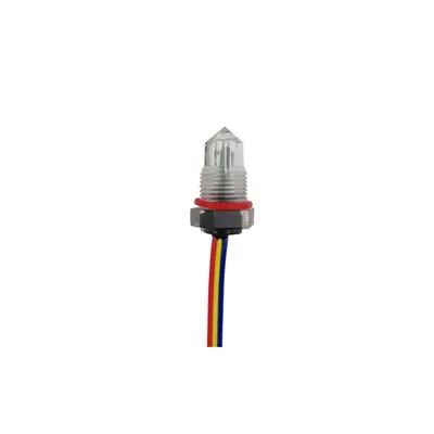
To implement an OS2 digital optical level sensor, power it from the logic rail at its rated voltage, tie its ground to your microcontroller, and read its open-collector/open-drain output through a pull-up (NPN) or pull-down (PNP) resistor into a GPIO - dry reads high, wet reads low (or inverted for PNP). This guide is the build-it companion to the OS2 overview: the same Optomax-family total-internal-reflection sensor, but focused on real wiring and working code rather than theory. A single OS2 on an Arduino takes about ten lines of digitalRead(); three OS2 sensors at low/mid/high become a pump controller in firmware. Because the sensor has internal hysteresis, you usually need no software debouncing. Confirm the exact OS2 supply voltage and output polarity (NPN vs. PNP) from the official Optomax datasheet before wiring (see disclaimer).
What You Need
Parts List
To build an OS2 digital level detector:
| Item | Purpose |
|---|---|
| OS2 digital optical sensor | The level switch |
| Microcontroller | Arduino Uno / Nano / ESP32 |
| Pull-up (NPN) or pull-down (PNP) | Bias the output |
| Logic rail | 3.3 V or 5 V per MCU |
| Common ground | Sensor ↔ MCU |
| Jumpers / PCB | Wiring |
One resistor, mostly: For an NPN (sinking) OS2, a 4.7 kΩ–10 kΩ pull-up from the output to the logic rail is all the extra hardware you need; the MCU reads a clean digital level. The sensor does the optical decision; the MCU just reads a pin.
Wiring
NPN (Sinking) - The Common Case
NPN OS2 to Arduino (5 V):
| OS2 Pin | To |
|---|---|
| V+ | 5 V (logic rail) |
| GND | Arduino GND |
| OUT | Through 10 kΩ pull-up to 5 V, then to GPIO 2 |
Dry = HIGH, wet = LOW: With the pull-up, the open-collector output sits at 5 V (HIGH, no liquid) and is pulled to GND (LOW, liquid present) when the tip is wetted. Read the GPIO; LOW means liquid. For a PNP (sourcing) OS2, invert: use a pull-down to GND and read HIGH when wet, LOW when dry - and confirm your MCU/PLC input type (sink vs. source) matches.
Arduino Sketch - Single Sensor
Read One OS2
cpp复制
// OS2 Digital Optical Level Sensor - single point (NPN open-collector) // Dry = HIGH (no liquid), Wet = LOW (liquid present) const int OS2_PIN = 2; // output through 10k pull-up to 5V void setup() { Serial.begin(9600); pinMode(OS2_PIN, INPUT); // external pull-up resistor } void loop() { int state = digitalRead(OS2_PIN); if (state == LOW) { Serial.println("LIQUID PRESENT"); } else { Serial.println("NO LIQUID (dry)"); } delay(500); }
That is the whole read: One digitalRead() per loop. The sensor's internal hysteresis already prevents chatter from bubbles or waves, so no debouncing is required for normal use. If your OS2 is PNP, swap the comparison (state == HIGH means wet).
Arduino Sketch - Three-Point Array
Low / Mid / High
cpp复制
// OS2 Digital Optical Level Sensor - 3-point (low/mid/high), NPN // LOW (on pin) = wet const int OS2_LOW = 2; const int OS2_MID = 3; const int OS2_HIGH = 4; void setup() { Serial.begin(9600); pinMode(OS2_LOW, INPUT); pinMode(OS2_MID, INPUT); pinMode(OS2_HIGH, INPUT); } void loop() { bool low = (digitalRead(OS2_LOW) == LOW); bool mid = (digitalRead(OS2_MID) == LOW); bool high = (digitalRead(OS2_HIGH) == LOW); // Pump runs when low is wet AND high is dry bool pumpOn = low && !high; // Optional alarm when mid point is reached bool alarm = mid; Serial.print("Low:"); Serial.print(low ? "WET " : "dry "); Serial.print("Mid:"); Serial.print(mid ? "WET " : "dry "); Serial.print("High:"); Serial.print(high ? "WET " : "dry "); Serial.print("Pump:"); Serial.print(pumpOn ? "ON " : "OFF"); Serial.print(" Alarm:"); Serial.println(alarm ? "YES" : "no"); // digitalWrite(PUMP_RELAY, pumpOn); delay(500); }
From three bits to pump logic: Each OS2 is an independent digital input; the pump and alarm rules live in firmware. Uncomment a digitalWrite() to a relay module on the pump line. Because each sensor is hysteretic, the bits stay clean through bubbles and waves - no per-sensor debouncing.
ESP32 Notes
3.3 V and Multiple Cores
Porting to ESP32:
| Item | Note |
|---|---|
| Logic rail | 3.3 V (not 5 V) |
| Pull-up | 10 kΩ to 3.3 V |
| Pins | Any GPIO (avoid strapping pins) |
| Loop | loop() or a task |
Mind the voltage: An ESP32 is 3.3 V - power the OS2 from 3.3 V (if its rated logic supply allows) and pull up to 3.3 V, never 5 V into a GPIO. The code is identical to the Arduino example; just change the pin numbers and the rail. If you need Wi-Fi alerts, move the print block into a task or use the loop() with a non-blocking timer.
Reading Logic
Dry/Wet Mapping
| Polarity | Dry | Wet | Read As |
|---|---|---|---|
| NPN | HIGH | LOW | LOW = wet |
| PNP | LOW | HIGH | HIGH = wet |
Invert per polarity: The only logic difference between NPN and PNP is which level means "wet." Pick the comparison to match your sensor's polarity (confirmed from the datasheet), and keep the rest of the firmware identical. A simple #define WET_STATE LOW at the top makes the polarity a one-line change.
Common Mistakes
What Breaks the Build
| Mistake | Symptom | Fix |
|---|---|---|
| Wrong polarity | Reads backwards | Match NPN/PNP to code |
| No pull-up/down | Floating, random | Add bias resistor |
| No common ground | Unstable reads | Tie grounds |
| 5 V into 3.3 V pin | Damage (ESP32) | Use 3.3 V rail |
| Dirty tip | Missed trips | Clean tip |
| Air bubble | False "dry" | Avoid trapped bubble |
Polarity and ground first: The two build-killers are a polarity mismatch (code says LOW=wet but the sensor is PNP, so it reads inverted) and a missing shared ground (floating, random values). Set the bias correctly, tie grounds, and the OS2 reads solid.
Validation
Prove It Before Deploy
| Step | Action |
|---|---|
| 1. Dry test | Tip in air → should read "no liquid" |
| 2. Wet test | Tip in water → should read "liquid" |
| 3. Oil test | Tip in oil → should also trigger |
| 4. Bubble test | Wave surface → no chatter |
| 5. Full-speed | Run at line/loop rate |
Wet both water and oil: Because the OS2 triggers on refractive index, not conductivity, it should read wet in both water and oil - a good sanity check that the tip is actually making optical contact. If it fails the wet test, the tip is dirty, not wetted, or the polarity is wrong.
What This Guide Adds
vs. the OS2 Overview
| Aspect | Overview | This Guide |
|---|---|---|
| Focus | Theory, family, specs | Wiring + code |
| Code | None | Arduino / ESP32 |
| Build | Conceptual | Hands-on |
| Use when | Choosing/learning | Implementing |
Two views, one sensor: The OS2 overview covers what the sensor is, its family place, and its specs; this guide covers how to actually wire and code it. Read the overview to choose, read this to build.
Frequently Asked Questions
Q1: How do I wire an OS2 digital optical level sensor to an Arduino?
Wire an NPN (sinking) OS2 to an Arduino by connecting its V+ to the 5 V logic rail, its GND to the Arduino GND, and its output through a 10 kΩ pull-up resistor to 5 V into a GPIO (e.g., pin 2). With pinMode(pin, INPUT) and a digitalRead(), the pin reads HIGH when the tip is dry (no liquid) and LOW when the tip is wetted (liquid present) - because the open-collector output pulls to ground when active. A PNP (sourcing) OS2 is the inverse: use a pull-down to GND and it reads HIGH when wet. Tie the grounds together, and the Arduino reads a clean digital level with no extra driver. Confirm the OS2's exact supply voltage and polarity from the datasheet before wiring.
Q2: Can I use multiple OS2 sensors for low/mid/high level?
Yes - connect each OS2 as an independent digital input (own pull-up/pull-down, shared ground) into separate GPIOs, then run the pump and alarm logic in firmware. A three-sensor low/mid/high setup reads three bits: pump ON when the low sensor is wet and the high sensor is dry, alarm when the mid sensor is wet. Because each OS2 has internal hysteresis, bubbles and waves do not cause chatter, so no software debouncing is needed. The sketch in this guide shows the exact logic - three digitalRead() calls, a pumpOn = low && !high rule, and an optional alarm flag.
Q3: Do I need to debounce an OS2 digital optical sensor in code?
Usually no. The OS2 has a comparator with hysteresis built in, which means a brief wave or bubble that changes the optical signal does not flip the output back and forth - the threshold has a small gap between turn-on and turn-off. That hysteresis is the hardware debounce, so a plain digitalRead() loop is stable in normal use. You might add a short software debounce only in unusually noisy mechanical environments, but for typical tank and appliance duty the internal hysteresis is sufficient. If you see chatter, check first for a dirty tip or an air bubble, not the code.
Q4: Will an OS2 work on an ESP32 at 3.3 V?
An OS2 will work on an ESP32 if you power it from the 3.3 V rail (assuming its logic supply rating allows 3.3 V) and pull up to 3.3 V, never 5 V into a GPIO - a 5 V signal can damage the ESP32's 3.3 V-tolerant pins. The reading code is identical to the Arduino example; only the pin numbers and the rail change. If the OS2's logic supply minimum is above 3.3 V, use a 5 V-tolerant MCU (like an Arduino Uno/Nano) or a level shifter rather than feeding 5 V directly to an ESP32 GPIO.
Q5: Why does my OS2 read "no liquid" even when the tip is submerged?
The usual causes are a dirty or coated tip, an air bubble trapped against the tip, or a polarity mismatch. The OS2 senses through its tip, so scale, biofilm, or residue on the face shifts the threshold and can blind it; clean the tip and retest. An air bubble pinned to the tip mimics a dry reading - reposition so liquid actually wets the face. Finally, if the sensor is PNP but your code assumes NPN (or vice-versa), the level is inverted and "wet" reads as "dry" - confirm the polarity from the datasheet and match the comparison in code. A quick dry/wet/oil test confirms which it is.
The Bottom Line
To implement an OS2 digital optical level sensor, connect its V+ to the logic rail, its GND to the microcontroller's ground, and its open-collector/open-drain output through a pull-up (NPN) or pull-down (PNP) resistor into a GPIO - then a single digitalRead() reports dry (HIGH for NPN) or wet (LOW for NPN), and three OS2 sensors at low/mid/high become a pump controller in firmware. This build-it guide is the hands-on companion to the OS2 overview: same Optomax-family total-internal-reflection sensor, but with concrete wiring (10 kΩ pull-up for NPN, pull-down for PNP), working Arduino code for single and three-point detection, ESP32 notes (use 3.3 V, never 5 V into a GPIO), and the reading logic (LOW = wet for NPN, HIGH = wet for PNP). The sensor's internal hysteresis means you normally need no software debouncing; validate with dry, wet (water and oil), and bubble tests; and watch the two build-killers - polarity mismatch and a missing shared ground. Confirm the exact OS2 supply voltage and output polarity from the official Optomax datasheet before wiring.
Last updated: August 2026
Disclaimer: This implementation guide describes building with the OS2 as a digital (logic-level) optical level sensor within the Optomax family (SST Sensing / Process Sensing Technologies). The Optomax family and its operating principle are established and documented (e.g., the Optomax Industrial Series part LLC200D324-003 carries 8–30 V DC, 7.5 mA max, 1 A sink/source, −25 to +80 °C class values). The specific "OS2" designation and its exact supply voltage, output polarity, temperature rating, and certification could not be pinned to a single public datasheet entry in the verification search and are presented here as Optomax Digital-family class values. The code examples are illustrative; confirm the exact OS2 variant parameters and your MCU's voltage tolerance against the official datasheet before wiring or powering. This guide is not affiliated with, endorsed by, or sponsored by SST Sensing, Process Sensing Technologies, or any distributor.