Photoelectric Water / Liquid Level Sensor For Arduino
In this guide: Using a photoelectric (optical) liquid level sensor with Arduino - what the sensor is, why it is a great Arduino fit, how to wire NPN and PNP versions, full example code (single sensor and a multi-sensor pump controller), common mistakes, applications, and the complete FAQ.
Photoelectric Water / Liquid Level Sensor For Arduino: Quick Answer
A photoelectric (optical) liquid level sensor is a solid-state, no-moving-parts point switch that detects liquid by total-internal-reflection - and it is an excellent Arduino sensor because it outputs a simple digital on/off signal. Wire the output to an Arduino digital pin: an NPN (open-collector) sensor needs a pull-up resistor (or INPUT_PULLUP), reads HIGH when dry and LOW when wet; a PNP sensor needs a pull-down and reads the opposite. The Arduino just does digitalRead() - no ADC, no calibration, no analog math. Because the decision is optical (refraction), it works on any liquid, including pure water that defeats conductive probes, and its built-in hysteresis means you do not need software debouncing.
What Is a Photoelectric Liquid Level Sensor?
Total Internal Reflection, in a Tip
Verified optical behavior:
| State | Light Path | Detector | Output |
|---|---|---|---|
| Dry (air) | Total internal reflection | Bright | "No liquid" |
| Wet (liquid) | Refraction escapes | Dim | "Liquid present" |
| Why any liquid | Refractive index breaks TIR | - | Water 1.33 / oil 1.46 |
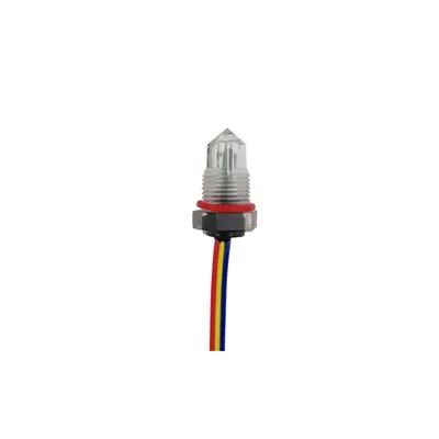
A light trap in a sealed tip: The sensor is a precision tip (glass or molded plastic) with an infrared LED (~850–950 nm) and a photodetector. In air (index ≈ 1.00) the light totally internally reflects back to the detector - dry. When liquid wets the tip, the liquid's higher index (water ≈ 1.33, oil ≈ 1.46) breaks the reflection and the light escapes - wet. The output flips. No float, no rod in the flow, no calibration. (Deep dive: How Optical Level Sensors Work.)
Why Photoelectric Fits Arduino
Digital, Fast, Any Liquid
Arduino-friendly traits:
| Trait | Arduino Benefit |
|---|---|
| Digital output | digitalRead(), no ADC |
| 5 V logic | Direct to GPIO |
| No calibration | No span math |
| Any liquid | Pure water OK |
| Hysteresis | No debounce code |
| Fast | Sub-ms response |
Made for a microcontroller: Three things make it ideal. First, the output is a clean digital on/off - you read it with digitalRead(), no analog-to-digital conversion or scaling. Second, most are 5 V-tolerant logic (or open-collector needing only a pull-up), so they connect straight to a GPIO. Third, the optical decision needs no zero/full calibration, and the built-in hysteresis prevents chatter at the threshold, so you skip software debouncing. It even works on pure/deionized water that conductive probes cannot sense. (See Optical Liquid Point Level Sensors.)
Wiring: NPN (Open-Collector)
Pull-Up, Read LOW = Wet
3-wire NPN connection:
| Wire | Connect To |
|---|---|
| Brown (V+) | 5 V (or sensor supply) |
| Blue (GND) | GND |
| Black (OUT) | GPIO + 10 kΩ pull-up to 5 V |
NPN = pull-up, wet is LOW: Most photoelectric liquid sensors are NPN (open-collector / open-drain). Power the sensor (Brown → 5 V, Blue → GND), then connect the output (Black) to a GPIO and to a 10 kΩ pull-up resistor to 5 V - or just enable the Arduino's internal pull-up in code. With the pull-up, the pin reads HIGH when dry and LOW when wet. That is the standard Arduino wiring. (See OS2 Digital Optical Level Sensor Implementation for the NPN/Arduino reference.)
Wiring: PNP (Sourcing)
Pull-Down, Read HIGH = Wet
3-wire PNP connection:
| Wire | Connect To |
|---|---|
| Brown (V+) | 5 V (or sensor supply) |
| Blue (GND) | GND |
| Black (OUT) | GPIO + 10 kΩ pull-down to GND |
PNP = pull-down, wet is HIGH: Some sensors are PNP (sourcing). Same power wires, but the output needs a 10 kΩ pull-down to GND (no internal pull-down on most Arduinos, so use an external resistor). With the pull-down, the pin reads LOW when dry and HIGH when wet - the opposite of NPN. Check the label: NPN vs PNP is the #1 thing to get right, or your logic will be inverted. (NPN/PNP explainer: Digital Output Level Sensor.)
Example Code: Single Sensor
Read Wet/Dry, Print It
cpp复制
// Photoelectric (optical) liquid level sensor - NPN, Arduino // Wiring: Brown -> 5V, Blue -> GND, Black -> D2 + 10k pull-up to 5V // NPN: dry = HIGH, wet = LOW #define SENSOR_PIN 2 // Uncomment for PNP (pull-down): wet = HIGH, dry = LOW // #define WET_STATE HIGH const bool WET_STATE = LOW; // NPN void setup() { Serial.begin(9600); pinMode(SENSOR_PIN, INPUT_PULLUP); // internal pull-up (NPN) } void loop() { bool wet = (digitalRead(SENSOR_PIN) == WET_STATE); if (wet) { Serial.println("Liquid detected at sensor"); } else { Serial.println("No liquid at sensor"); } delay(500); }
What it does: Enable the internal pull-up, read the pin, and compare to WET_STATE. For NPN, wet = LOW; flip the constant (or the PNP wiring) for PNP. No debounce needed - the sensor's hysteresis handles threshold chatter. Print to Serial Monitor to watch it trip as you raise and lower the liquid past the tip. This is the entire application for a single point alarm.
Example Code: Pump Controller
Low + High, Drive a Relay
cpp复制
// Optical liquid level sensors + Arduino pump controller // NPN sensors: LOW = wet // LOW sensor (D2) = pump ON when wet; HIGH sensor (D3) = pump OFF when wet #define LOW_SENSOR 2 #define HIGH_SENSOR 3 #define PUMP_RELAY 8 const bool WET = LOW; // NPN void setup() { pinMode(LOW_SENSOR, INPUT_PULLUP); pinMode(HIGH_SENSOR, INPUT_PULLUP); pinMode(PUMP_RELAY, OUTPUT); digitalWrite(PUMP_RELAY, LOW); // pump off } void loop() { bool lowWet = (digitalRead(LOW_SENSOR) == WET); bool highWet = (digitalRead(HIGH_SENSOR) == WET); // Pump runs only when liquid is at the LOW mark but NOT yet at the HIGH mark bool pumpOn = lowWet && !highWet; digitalWrite(PUMP_RELAY, pumpOn ? HIGH : LOW); delay(200); }
Two sensors, one pump: Place a LOW sensor at the minimum level and a HIGH sensor at the maximum. The pump runs only while the low mark is wet and the high mark is still dry - a simple fill-or-drain controller. The relay (driven by PUMP_RELAY) should be a separate relay module with its own power; never power a pump straight from an Arduino pin. Add a flyback diode across the relay coil. This pattern scales to three or four sensors for staged alarms.
Calibration and Setup
Just Place It
No span to set:
| Step | Action |
|---|---|
| Mount | Tip at set height |
| Wire | NPN pull-up / PNP pull-down |
| Verify | Wet/dry in Serial |
| Seal | Keep connector dry |
| Clean | Wipe tip if coated |
Fit and forget: Unlike a 4–20 mA transmitter, an optical point sensor needs no empty/full calibration - you mount the tip where you want the trip and read the digital state. Verify the wet/dry transition in the Serial Monitor as you move liquid past the tip, keep the electrical connector above the splash line, and wipe the tip if a coating builds up. That is the whole setup. (Placement guide: Optical Liquid Level Sensor.)
Common Mistakes
Don't Do These
Arduino pitfalls:
| Mistake | Fix |
|---|---|
| No pull-up (NPN) | Add 10 k or INPUT_PULLUP |
| Wrong NPN/PNP | Check label; flip WET_STATE |
| 5 V only | Don't feed 12 V to GPIO |
| Water on connector | Mount above splash |
| Floating input | Always pull up/down |
| Pump on GPIO | Use relay module |
The usual errors: The top mistake is forgetting the pull-up on an NPN open-collector output - without it the pin floats and reads garbage; INPUT_PULLUP fixes it. The second is mixing up NPN and PNP, which inverts your logic (just flip WET_STATE). Never feed the sensor's higher supply (some run 12–30 V) into a 5 V GPIO - level-shift or use the sensor's 5 V mode. Keep the connector dry, always pull the input, and drive the pump through a relay, never the pin. (See Water Level Sensor Arduino for the broad sensor menu.)
Applications
Where Makers Use It
| Project | Use |
|---|---|
| Plant watering | Tank low alarm |
| Aquarium | Top-off control |
| Sump | Overflow / dry-run |
| RO / filtration | Low-pressure trip |
| Coffee / beverage | Reservoir guard |
| Battery bank | Acid leak alarm |
Small tanks, fast trips: Makers use optical liquid sensors for plant-watering reservoir low alarms, aquarium auto-top-off, sump overflow or dry-run protection, RO-system low-pressure trips, and - with the right tip - battery-acid leak alarms. The digital output and any-liquid behavior make it a drop-in for almost any small-tank point detection where a float would stick or a conductive probe would fail on pure water. (Acid context: Install Inverter Battery Water Level Sensor.)
Photoelectric vs. Other Arduino Sensors
Quick Compare
| Sensor | Arduino Effort | Liquid Limit |
|---|---|---|
| Photoelectric (optical) | Digital, easy | Point only |
| Float switch | Digital, easy | Point, can stick |
| Capacitive | Analog or digital | Point/cont, teardown |
| Resistive | Analog, corrodes | Point, conduct only |
| Ultrasonic | Pulse timing | Continuous, foam blind |
Pick optical for clean point trips: For a simple point alarm, photoelectric and float are both digital-easy, but optical has no moving part to stick. Capacitive and resistive need analog reads (and resistive corrodes); ultrasonic gives continuous level but needs pulse timing and is fooled by foam. Choose optical when you want a sealed, any-liquid, no-calibration point trip and an effortless digitalRead(). (Full menu: Water Level Sensor Arduino.)
Frequently Asked Questions
Q1: How do I connect a photoelectric liquid level sensor to an Arduino?
Power it (Brown → 5 V, Blue → GND) and connect the output (Black) to a digital GPIO. For an NPN (open-collector) sensor, add a 10 kΩ pull-up to 5 V - or use pinMode(pin, INPUT_PULLUP) - and the pin reads HIGH when dry, LOW when wet. For a PNP (sourcing) sensor, use a 10 kΩ pull-down to GND instead, and the logic inverts (LOW dry, HIGH wet). Then digitalRead() the pin. No ADC and no calibration are needed; the output is already a clean digital on/off.
Q2: Does the optical sensor work with pure or deionized water?
Yes - that is a key advantage. The sensor decides by optics (refraction at the tip), not by electrical conductivity, so it detects pure/deionized water, tap water, and oil alike. A conductive (resistive) probe fails on pure water because there is too little conductivity to complete the circuit; an optical TIR tip does not care. Just make sure the tip material (glass or food-safe PP/PSU) is compatible with the fluid, and keep the tip clean.
Q3: Why don't I need to debounce the reading in code?
Because the sensor has built-in hysteresis: it switches ON at one wetting threshold and OFF at a slightly different drying threshold, so it will not chatter on/off at the boundary. A float or mechanical switch often needs software debouncing; an optical solid-state switch does not. You can still add a short delay (as in the examples) to slow the Serial output, but you do not need a debounce counter to get a stable reading.
Q4: Can I use more than one optical sensor with one Arduino?
Yes, easily - each sensor is just another digital input. Connect each output to its own GPIO with the correct pull-up (NPN) or pull-down (PNP), then read them independently. Two sensors give a low/high fill controller (pump runs only between them); three or four give staged alarms. The examples show both a single sensor and a two-sensor pump controller. Just keep each input pulled and watch the NPN/PNP polarity per sensor.
Q5: Can the Arduino power the sensor and the pump directly?
The Arduino can power the small sensor (it draws only a few milliamps) from its 5 V rail, but never power a pump from a GPIO pin - a pump draws far too much current and will damage the board. Drive the pump through a relay module (or MOSFET) with its own supply, and place a flyback diode across the relay coil. The examples show the pump controlled by a relay on a separate pin and power source.
The Bottom Line
A photoelectric (optical) liquid level sensor is a near-ideal Arduino sensor: a solid-state, no-moving-parts point switch that outputs a clean digital on/off by total-internal-reflection, so the Arduino just does digitalRead() with no ADC or calibration. Wire an NPN (open-collector) output with a pull-up (or INPUT_PULLUP) and read LOW = wet; wire a PNP with a pull-down and read HIGH = wet. Built-in hysteresis means no software debounce, and the optical decision works on any liquid - including pure water that defeats conductive probes. Use one sensor for a point alarm, or two or more for a low/high pump controller (driven through a relay, never a GPIO). Mind the pull-up/pull-down and the NPN/PNP polarity, keep the connector dry, and the sensor is fit-and-forget. (For the full sensor menu, see Water Level Sensor Arduino.)
Last updated: August 2026
Disclaimer: This guide explains using a photoelectric (optical, total-internal-reflection) liquid level sensor with an Arduino for educational and maker purposes. Technical anchors used (IR TIR: dry = total internal reflection / wet = refraction escape; refractive index air ≈ 1.00, water ≈ 1.33, oil ≈ 1.46; IR ~850–950 nm; hysteresis; NPN open-collector needs pull-up, PNP needs pull-down; ~1 A / 8–30 V class supply) are established optical-switch facts. Wire colors (Brown/Blue/Black) follow the common IEC sensor convention but vary by manufacturer - confirm against the specific sensor's datasheet. The example code is illustrative; verify pin assignments, supply voltage (do not feed >5 V into a GPIO), and relay/pump current before building. Product names are trademarks of their respective owners; this guide is not affiliated with or sponsored by any manufacturer.