The Ultimate Guide to Liquid Level Switches
The complete A-to-Z reference to liquid level switches - what they are, how they work, the full family tree, wiring, applications, selection, installation, maintenance, troubleshooting, and safety: the core definition (a liquid level switch is a device that detects whether a liquid has reached a specific level - the set point - and changes an electrical output state in response; it is the point-level member of the level measurement family, answering the binary question "is the level there?" rather than the numeric "how much is there?" - and its job is alarm, pump control, low-level cutoff, and overflow protection, not inventory), the four core mechanisms (buoyancy - the float rides the surface and its magnet trips a sealed reed switch; vibration - the fork's piezoelectric crystals resonate and the liquid damps the oscillation; light - the optical TIR sensor's infrared beam refracts away when liquid covers the prism; conductivity - the liquid completes the circuit between two electrodes - each mechanism is a way to convert "the liquid is here" into a clean electrical state), the family tree (mechanical: the vertical float, the horizontal pivot float, the suspended float, the latching float, the mercury tilt float; solid-state: the vibrating fork, the optical TIR, the conductivity probe, the capacitive switch - with the solid-state members winning where the mechanical members' moving parts fail), the output and contact types (SPDT, NO/NC, latching, dry contact, PNP/NPN, NAMUR - the output is the handshake with the controller), the wiring basics (the NO/NC pair, the pull-up resistor, the controller input, the flyback diode on relay coils), the applications table (sump pumps, boiler low-water cutoff, overflow protection, tank alarms, leak detection, washing machines, coffee makers, humidifiers - the consumer appliance switches are the same physics as the industrial ones), the selection shortcut (five questions that route to the right family - with the full funnel in the selection guide), the installation rules (mounting, orientation, cable entry, the stilling well, minimum distance from the inlet), the maintenance and troubleshooting table (coating, stuck floats, failed reeds, leaking probes - the failure modes and their fixes), the safety section (hazardous areas: NAMUR + Ex ia, the low-water cutoff as a safety device, the independent-switch rule), the FAQ, and the bottom line.
The Ultimate Guide to Liquid Level Switches - Quick Answer
A liquid level switch is a device that detects whether a liquid has reached a specific level - the set point - and changes an electrical output state in response: the point-level member of the level measurement family, answering the binary question "is the level there?" rather than the numeric "how much is there?" - and its jobs are alarm, pump control, low-level cutoff, and overflow protection, not inventory. The switch converts "the liquid is here" into a clean electrical state through one of four core mechanisms. Buoyancy: the float rides the surface, and its magnet trips a sealed reed switch inside the stem - the oldest and cheapest way, with no power at the sensing point. Vibration: the fork's piezoelectric crystals resonate at its natural frequency, and the liquid damps the oscillation - the coating-tolerant industrial standard. Light: the optical TIR sensor's infrared beam refracts away when liquid covers the prism - the no-moving-parts clean-liquid specialist. Conductivity: the liquid completes the circuit between two electrodes - the cheapest multi-point option for conductive liquids. The family tree splits into mechanical (vertical float, horizontal pivot float, suspended float, latching float) and solid-state (vibrating fork, optical TIR, conductivity probe, capacitive switch), and the solid-state members win where the mechanical members' moving parts fail. The output is the handshake with the controller - dry contact, PNP/NPN, or NAMUR - and the contact types (SPDT, NO/NC, latching) decide what the state means. The applications run from the washing machine and the coffee maker to the sump pump and the boiler low-water cutoff - the consumer appliance switch and the industrial switch are the same physics. The one-sentence rule: the liquid level switch is the point-level workhorse - the cheapest, simplest, most reliable way to ask a liquid a yes/no question. (The family map: Float Switches & Level Sensors Archives; the selection procedure: Level Sensor & Switches Selection Guide; the switch taxonomy: What Are the Different Types of Switches?.)
What Is a Liquid Level Switch?
The Binary Member of the Level Family
The definition table (Featured Snippet):
| Term | What it means |
|---|---|
| Liquid level switch | Detects whether liquid reached a set point; changes an output state |
| Set point | The level where the switch actuates |
| Point level | The category: binary detection at a point |
| Continuous level | The sibling category: numeric measurement of the level |
| Actuation | The state change (contact closes or opens, output switches) |
A liquid level switch is the point-level workhorse - it asks "is the liquid there?" and answers with a contact state, not a number: A liquid level switch detects whether a liquid has reached a specific level - the set point - and changes an electrical output state in response. It is the point-level member of the level measurement family: it answers the binary question "is the level there?" with a state - contact closed or open, output on or off - rather than the numeric question "how much is there?", which belongs to the continuous transmitter. The set point is the level where the switch actuates, and the actuation is the state change - the contact closes, the transistor switches, the current steps. The point-level category is the oldest and most reliable part of level measurement: a binary answer needs no calibration, no math, and no power at the sensing point in the mechanical members. The jobs follow from the binary nature: alarm, pump control, low-level cutoff, and overflow protection - the moments where the level crosses a line - not inventory or trending, which need the number. The one-sentence summary: the liquid level switch is the binary member of the level family - it trades the numeric detail of the transmitter for the simplicity, cost, and reliability of a state change. (The point-versus-continuous fork: Level Sensor & Switches Selection Guide; the family matrix: Float Switches & Level Sensors Archives; the switch taxonomy: What Are the Different Types of Switches?.)
The Four Core Mechanisms
Buoyancy, Vibration, Light, and Conductivity
The mechanism table (Featured Snippet):
| Mechanism | How it works | The signature | The weakness |
|---|---|---|---|
| Buoyancy (float) | The float rides the surface; its magnet trips a sealed reed switch | Simplest, cheapest, no power at the sensing point | Moving part: coating, jams, turbulence |
| Vibration (fork) | Piezoelectric crystals resonate; liquid damps the oscillation | Coating-tolerant, no moving part, any liquid | Needs a port; bridging in solids |
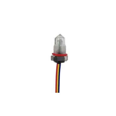
| Light (optical TIR) | Infrared beam refracts away when liquid covers the prism | No moving parts, tiny, fast, clean liquid | Coating kills it; clean liquid only |
| Conductivity | Liquid completes the circuit between electrodes | Cheapest multi-point, no moving parts | Conductive liquid only; electrodes foul |
The four mechanisms are four ways to convert "the liquid is here" into a clean electrical state - and each one's weakness is the next one's reason to exist: The four core mechanisms are the ways a liquid level switch converts "the liquid is here" into a clean electrical state. Buoyancy - the float rides the surface, and its magnet trips a sealed reed switch inside the stem: the oldest, simplest, cheapest mechanism, with no power at the sensing point (the reed is passive and sealed) - its weakness is the moving part: coating changes the float's buoyancy, jams stick it, and turbulence rocks it. Vibration - the fork's piezoelectric crystals drive it at its natural resonance, and the liquid damps the oscillation (the controller sees the frequency change and switches): the coating-tolerant, no-moving-parts industrial standard that works on any liquid - its weakness is the port it needs and bridging when solids pack between the tines. Light - the optical TIR sensor's infrared beam travels inside a prism and refracts away when liquid covers the tip (total internal reflection breaks): the no-moving-parts, tiny, fast clean-liquid specialist - its weakness is coating, which blocks the prism. Conductivity - the liquid completes the circuit between two electrodes (the controller reads the current): the cheapest multi-point option, one controller reading several electrode lengths - its weakness is that the liquid must be conductive, and the electrodes foul. The reading: each mechanism's weakness is the next one's reason to exist - float for clean and cheap, fork for dirty and industrial, optical for clean and tiny, conductivity for conductive and multi-point. (The float anatomy: Float Switches & Level Sensors Archives; the fork and optical: Industrial Level Switches: Float, Capacitive, and More; the optical pair: How Optical Liquid Level Sensors Work.)
The Family Tree
Mechanical vs Solid-State
The family tree (Featured Snippet):
| Family | Member | How it works | The niche |
|---|---|---|---|
| Mechanical | Vertical float | A ring magnet slides along a stem, tripping reed switches | The classic; simple set point |
| Mechanical | Horizontal pivot float | The float pivots on a hinge, tripping a micro switch or reed | Side-mount tanks; compact |
| Mechanical | Suspended float | The float hangs on a cable with a counterweight | Sump pumps; the standard |
| Mechanical | Latching float | A second magnet holds the state until the level moves far | Pump differential (hysteresis) |
| Mechanical | Mercury tilt float | A mercury switch tilts with the float | Being phased out (environmental) |
| Solid-state | Vibrating fork | Piezoelectric resonance damped by liquid | Dirty, coating liquids; industrial |
| Solid-state | Optical TIR | Infrared refraction changes at the prism | Clean liquid; tiny spaces |
| Solid-state | Conductivity | Electrodes complete the circuit through the liquid | Conductive liquid; multi-point |
| Solid-state | Capacitive | The liquid changes the probe's capacitance | Simple continuous-ish; non-conductive |
The family tree splits into mechanical and solid-state - the mechanical members are the classics with moving parts, and the solid-state members win wherever the moving part fails: The liquid level switch family tree splits into two branches. The mechanical branch - the classics, driven by moving parts. The vertical float: a ring magnet rides a stem and trips reed switches at the set points - the simplest point switch there is. The horizontal pivot float: the float pivots on a hinge and trips a micro switch or reed - the side-mount, compact answer for tanks without top access. The suspended float: the float hangs on a cable with a counterweight - the standard for sump pumps, where the switch travels with the surface. The latching float: a second magnet holds the state until the level moves past the release point - the built-in hysteresis that makes pump differentials without a controller. The mercury tilt float: a mercury switch tilts with the float - the environmentally problematic member, being phased out. The solid-state branch - no moving parts, driven by physics. The vibrating fork, the optical TIR, the conductivity probe, and the capacitive switch. The reading: the mechanical members win on simplicity, cost, and passive sensing; the solid-state members win wherever the moving part fails - coating, jams, vibration, and speed. (The five floats: Float Switches & Level Sensors Archives; the solid-state details: Industrial Level Switches: Float, Capacitive, and More; the hysteresis rule: Level Switches for Tanks for Automation.)
Contacts and Outputs
SPDT, NO/NC, Latching, PNP/NPN, NAMUR
The output table (Featured Snippet):
| Output | What it carries | Where it goes | The detail |
|---|---|---|---|
| Dry contact (SPDT) | A contact state | Relays, controllers, PLC inputs | Common ©, normally open (NO), normally closed (NC) |
| NO / NC | The resting state | Decides fail-safe logic | NC = fails safe on wire break |
| Latching | A held state | Pump differential control | Two set points, one contact |
| PNP / NPN | A transistor state | PLC and controller inputs | Sourcing vs sinking - match the input |
| NAMUR | 8/16 mA current steps | IS barriers, hazardous areas | 0 mA = wire break (the fault state) |
The output is the handshake with the controller - the contact types decide what the state means, and the output types decide how it travels: The contacts and outputs of a liquid level switch are the handshake with the controller. The dry contact - the classic SPDT (single-pole double-throw): three terminals - common ©, normally open (NO), and normally closed (NC) - and the state is a contact, open or closed, rated for the load. The NO/NC pair decides the fail-safe logic: an NC contact reads "closed" when the level is safe and opens on the alarm - so a wire break fails the circuit into the alarm state, the fail-safe direction. The latching contact - the state is held until the level moves past a second set point: the pump differential, where the pump starts at the high point and stops at the low point without a controller. The PNP/NPN transistor output - a sinking or sourcing state for the PLC input world: match the sensor to the input (a sinking input wants a PNP sensor). The NAMUR output - 8/16 mA current steps through an intrinsically safe barrier: the hazardous-area output, where 0 mA means wire break - the fault state that a dry contact cannot show. The reading: choose the contact by the logic (NO/NC, latching), and the output by the controller (dry, PNP/NPN, NAMUR) - and for fail-safe, the NC contact and the NAMUR fault state are the friends. (The NAMUR state: Intrinsically Safe Level Switch; the contact taxonomy: What Are the Different Types of Switches?; the wiring: How to Read a Schematic.)
Wiring Basics
The NO/NC Pair, the Pull-Up, and the Flyback Diode
The wiring table (Featured Snippet):
| Element | What it does | The rule |
|---|---|---|
| NO/NC wiring | The contact's resting state defines the logic | NC fails safe on wire break |
| Pull-up / pull-down | Defines the resting input level | Needed for dry contact and open-collector outputs |
| Controller input | Reads the state | Match PNP/NPN to the input type |
| Flyback diode | Across the relay coil | Clamps the inductive spike; protects the driver |
| Cable entry | The wire enters the housing | Seal it - moisture is the #1 switch killer |
The wiring is simple - but the NC fail-safe direction, the pull-up, and the flyback diode are the three details that separate a reliable installation from a flaky one: The wiring basics of a liquid level switch are simple, with three details that matter. The NO/NC pair: the resting state defines the logic - a normally closed contact reads "safe" as closed and opens on the alarm, so a wire break fails the circuit into the alarm state; the fail-safe direction for overflow and low-level protection. The pull-up and pull-down resistors: a dry contact or open-collector output leaves the input floating when the contact opens - the pull-up (or pull-down) defines the resting level so the input reads a defined state, not noise. The controller input: match the sensor's output to the input type - a sinking PLC input wants a PNP sensor, a sourcing input wants an NPN sensor - the mismatch is the silent killer of sensor wiring. The flyback diode: across the relay coil in the switch's output circuit, it clamps the inductive spike when the coil de-energizes - without it, the driver transistor dies on the first actuation. The cable entry: the wire enters the housing through a gland - seal it, because moisture at the gland is the number-one killer of level switches. The reading: wire the fail-safe direction, pull up the floating input, match the transistor type, protect the coil, and seal the gland. (The flyback anchor: Why Flyback Diodes Are Required Across Relay Coils; the pull-up rules: Pull-Up and Pull-Down Resistors; the input matching: Open Collector vs Push-Pull Output.)
The Applications Table
From the Washing Machine to the Boiler Cutoff
The applications table (Featured Snippet):
| Application | The switch | The job |
|---|---|---|
| Sump pump | Suspended float | Start at high level, stop at low |
| Boiler low-water cutoff | Float or probe | Shut the burner off before the boiler runs dry |
| Overflow protection | Independent point switch | Alarm or shut the inlet valve (API 2350) |
| Tank alarm | Float or optical | High-level alarm on storage tanks |
| Leak detection | Optical TIR | Detect liquid in the drip tray |
| Washing machine | Pressure-based level sensor | Fill to the programmed level |
| Coffee maker | Float or optical | Empty / full indication |
| Humidifier | Float | Water-level cutoff |
| Automotive | Float in the tank | Fuel level and low-fuel warning |
The applications run from the kitchen counter to the boiler room - the consumer appliance switch and the industrial switch are the same physics, packaged differently: The applications of the liquid level switch run the whole scale of liquid handling. The sump pump - the suspended float starts the pump at the high level and stops it at the low, the classic float application. The boiler low-water cutoff - a float or probe switch shuts the burner off before the boiler runs dry: the safety device that turns a level switch into a life-safety component. The overflow protection - an independent point switch alarms or shuts the inlet valve: the API 2350 architecture, where the protection is independent of the transmitter's reading. The tank alarm - a float or optical switch raises the high-level alarm on storage tanks. The leak detection - an optical TIR switch senses liquid in the drip tray under a pump or a machine. The washing machine - a pressure-based level sensor fills the tub to the programmed level, the consumer version of the hydrostatic principle. The coffee maker - a float or optical switch gives the empty and full indication. The humidifier - a float gives the water-level cutoff. The automotive - the float in the fuel tank drives the gauge and the low-fuel warning, the highest-volume float switch in the world. The reading: the physics is identical from the coffee maker to the boiler - the consumer appliance switch and the industrial switch are the same mechanisms, packaged for different environments. (The appliance edition: Water Level Sensor for Washing Machine; the boiler cutoff: Boiler Low Water Cutoff; the overflow rule: Intrinsically Safe & Explosion-Proof Level Solutions.)
The Selection Shortcut
Five Questions to the Right Family
The shortcut table (Featured Snippet):
| Question | The answer routes to |
|---|---|
| Is the liquid clean and non-coating? | Optical TIR or float |
| Is the liquid dirty, coating, or slurry? | Vibrating fork |
| Is the liquid conductive? | Conductivity (multi-point) |
| Is it a hazardous area? | NAMUR output + Ex-certified versions |
| Is it fail-safe critical? | NC contact, independent switch |
The selection shortcut is five questions - and the full five-step funnel lives in the selection guide: The selection shortcut for a liquid level switch is five questions. Is the liquid clean and non-coating? - the optical TIR or the float. Is the liquid dirty, coating, or slurry? - the vibrating fork, which tolerates the coating and has no moving part. Is the liquid conductive? - the conductivity switch, the cheapest multi-point option. Is it a hazardous area? - the NAMUR output with the Ex-certified versions, through an intrinsically safe barrier. Is it fail-safe critical? - the NC contact, and the independent-switch architecture where the safety function is separate from the process function. The shortcut is the front door to the full selection procedure: the five-step funnel - liquid properties, process conditions, point-versus-continuous, output, environment - lives in the selection guide, and it ends where the shortcut begins. The reading: answer the five questions and the family picks itself; go to the funnel when the process is demanding. (The full funnel: Level Sensor & Switches Selection Guide; the hazardous edition: Hazardous Location Guide to Liquid Level Sensors; the IS deep dive: Intrinsically Safe Level Switch.)
Installation Rules
Mounting, Orientation, and the Stilling Well
The installation table (Featured Snippet):
| Rule | The detail |
|---|---|
| Mount vertically | Floats need the stem vertical; the magnet must slide freely |
| Respect the minimum distance | Keep the switch away from the inlet flow and the pump vortex |
| Use a stilling well | Calms turbulence; the float reads a true surface |
| Seal the cable entry | Moisture at the gland is the #1 killer |
| Support long probes | Probes over 3 feet need support against flow forces |
| Check the set point | Verify the actuation level matches the process requirement |
The installation rules are the difference between a switch that works for years and one that fails in months - orientation, distance, the stilling well, and the seal: The installation rules for a liquid level switch are the difference between years of service and months of failure. Mount vertically - the floats need the stem vertical so the magnet slides freely; a tilted float sticks. Respect the minimum distance - keep the switch away from the inlet flow (the falling liquid splashes and rocks the float) and the pump vortex (the swirling surface gives false actuations). Use a stilling well - the tube calms the turbulence and the float reads a true surface, the standard fix for agitated tanks. Seal the cable entry - moisture at the gland is the number-one killer, and the seal is the only defense. Support long probes - probes over about 3 feet need support against flow forces, which bend and fatigue them. Check the set point - verify the actuation level against the process requirement before commissioning, with water or the actual liquid. The reading: mount it vertical, keep it away from the inlet and the vortex, calm the surface with the well, seal the gland, support the probe, and verify the set point. (The stilling well: Measure Liquid Level with Pressure Sensors; the tank automation rules: Level Switches for Tanks for Automation; the data sheet: Sensor Data Sheet: How to Read and Use One.)
Maintenance and Troubleshooting
Coating, Stuck Floats, Failed Reeds, Leaking Probes
The troubleshooting table (Featured Snippet):
| Symptom | The cause | The fix |
|---|---|---|
| No actuation | Stuck float, failed reed, wrong wiring | Check the float travel; test the reed with a magnet; check the wiring |
| Intermittent actuation | Turbulence, loose magnet, marginal set point | Stilling well; check the float; verify the set point |
| Stuck on / stuck off | Coating, bridging (fork), welded contacts | Clean; check the fork's tines; replace the switch |
| Reading the foam | Foam on the surface fools the float and the fork | Change the principle or add a stilling well |
| Moisture inside | Failed gland seal | Replace the seal; dry and test |
| Premature reed failure | Switching a load above the rating | Add a relay or an SSR; respect the contact rating |
The troubleshooting table is the service page - the six failure modes of a liquid level switch, each with a cause and a fix, and most of them trace back to coating, turbulence, or wiring: The maintenance and troubleshooting table for liquid level switches covers the six common failure modes. No actuation - a stuck float, a failed reed, or wrong wiring: check the float travel, test the reed with a magnet (it should click and read), and check the wiring. Intermittent actuation - turbulence rocking the float, a loose magnet, or a marginal set point: add the stilling well, check the float, verify the set point. Stuck on or stuck off - coating on the float, bridging between the fork's tines, or welded contacts: clean it, check the tines, and replace the switch if the contacts are welded. Reading the foam - foam on the surface fools the float and the fork: change the principle (radar, guided wave) or add the stilling well. Moisture inside - a failed gland seal: replace the seal, dry the switch, and test. Premature reed failure - switching a load above the contact rating: the reed is a delicate dry-circuit contact - add a relay or an SSR and respect the rating. The reading: most failures trace back to coating, turbulence, or wiring - and the fixes are cleaning, the stilling well, and the relay. (The contact ratings: Switch Contact Ratings; the relay protection: Why Flyback Diodes Are Required Across Relay Coils; the dry-circuit rule: Reed Switch Contact Ratings.)
The Safety Section
Hazardous Areas, the Low-Water Cutoff, and the Independent Switch
The safety table (Featured Snippet):
| Safety topic | The rule |
|---|---|
| Hazardous areas | NAMUR output through an IS barrier; Ex ia reaches Zone 0; Ex d for Zone 1/2 |
| Low-water cutoff | The switch is a safety device - test it regularly, never bypass it |
| Independent protection | The safety switch is separate from the process transmitter (API 2350) |
| Fail-safe logic | NC contact fails into the alarm state on wire break |
| Cable and gland | The seal and the cable rating are part of the certification |
The safety section is where the level switch stops being a convenience and becomes a safety device - the low-water cutoff, the independent switch, and the fail-safe direction: The safety section of the liquid level switch is where it stops being a convenience and becomes a safety device. Hazardous areas: the switch needs the NAMUR output through an intrinsically safe barrier - Ex ia certification reaches Zone 0 (the milliwatt principles: float with reed, optical, fork), and Ex d covers Zone 1/2 for the higher-power members. The low-water cutoff: the boiler cutoff is a safety device - test it regularly and never bypass it, because its only job is to prevent the boiler from running dry. Independent protection: the safety switch is separate from the process transmitter - the API 2350 overfill architecture, where the high-level switch does not share the transmitter's path. Fail-safe logic: the NC contact fails into the alarm state on a wire break - the direction that makes a failure visible. The cable and gland: the seal and the cable rating are part of the certification - a certified switch with an uncertified cable entry is not a certified installation. The reading: in the safety roles, the switch is the last line - test it, never bypass it, keep it independent, wire it fail-safe, and keep the installation certified. (The hazardous-area map: Hazardous Location Guide to Liquid Level Sensors; the IS deep dive: Intrinsically Safe Level Switch; the API 2350 architecture: Intrinsically Safe & Explosion-Proof Level Solutions.)
FAQ
Q1: What is a liquid level switch and how does it work?
A liquid level switch detects whether a liquid has reached a set point and changes an electrical output state. It works through one of four mechanisms: buoyancy (a float's magnet trips a reed switch), vibration (the liquid damps a resonating fork), light (liquid refracts an optical TIR beam), or conductivity (the liquid completes a circuit between electrodes).
Q2: What is the difference between a level switch and a level transmitter?
A level switch answers the binary question "is the level there?" with a contact state - for alarms, pump control, and cutoffs. A level transmitter answers the numeric question "how much is there?" with a measurement - for inventory and process control. For a protected tank, use both, independently.
Q3: Which liquid level switch is the most reliable?
The vibrating fork is the industrial standard for reliability: no moving parts, coating-tolerant, and works on any liquid. The float switch is the most reliable within its envelope - clean liquid, calm surface - and the simplest, with no power at the sensing point.
Q4: Can a liquid level switch work in a hazardous area?
Yes - with the certified versions: NAMUR output through an intrinsically safe barrier (Ex ia, reaching Zone 0), or Ex d certified switches for Zone 1/2. Verify the certificate covers your zone, gas group, and temperature class.
Q5: Why does my float switch keep sticking?
The classic causes are coating on the float (changes its buoyancy), a tilted stem (the magnet cannot slide), or turbulence rocking the float. Fix the coating with a fork switch, mount the stem vertically, and calm the surface with a stilling well.
The Bottom Line
A liquid level switch is a device that detects whether a liquid has reached a set point and changes an electrical output state - the point-level workhorse of the level measurement family, answering the binary question "is the level there?" with a contact state instead of a number. The four core mechanisms are buoyancy (the float's magnet trips a sealed reed), vibration (the liquid damps a resonating fork), light (liquid refracts the optical TIR beam), and conductivity (the liquid completes the electrode circuit) - four ways to convert "the liquid is here" into a clean electrical state, and each one's weakness is the next one's reason to exist. The family tree splits into mechanical (vertical, horizontal pivot, suspended, latching, mercury tilt floats) and solid-state (vibrating fork, optical TIR, conductivity, capacitive) - the solid-state members win wherever the moving part fails. The contacts and outputs - SPDT, NO/NC, latching, PNP/NPN, NAMUR - are the handshake with the controller, and the NC fail-safe direction and the NAMUR fault state are the safety friends. The wiring is simple, with three details that matter: the fail-safe direction, the pull-up, and the flyback diode on the relay coil. The applications run from the washing machine and the coffee maker to the sump pump and the boiler low-water cutoff - the same physics, packaged for different environments. The selection is five questions, and the full funnel lives in the selection guide. The installation is orientation, distance, the stilling well, and the seal. The troubleshooting is coating, turbulence, wiring, and moisture. The safety section is where the switch becomes a safety device: the hazardous-area certification, the low-water cutoff that is never bypassed, the independent protection of API 2350, and the fail-safe direction. The one-sentence rule: the liquid level switch is the point-level workhorse - the cheapest, simplest, most reliable way to ask a liquid a yes/no question. (The family map: Float Switches & Level Sensors Archives; the selection procedure: Level Sensor & Switches Selection Guide; the hazardous edition: Hazardous Location Guide to Liquid Level Sensors.)
Last updated: August 2026
Disclaimer: This article is an educational reference guide to liquid level switches, for general reference. The mechanisms (buoyancy, vibration, light, conductivity), the family tree, the contact and output types, the wiring guidance, the applications, the installation rules, and the troubleshooting guidance reflect common engineering knowledge and vary by manufacturer, model, and application; always verify the specific device's data sheet, ratings, and certification with the manufacturer's documentation and the applicable standards and codes. Selection, installation, and wiring must be performed by qualified personnel, and safety devices such as low-water cutoffs must be tested and maintained per their instructions.