What Are Solid State Diodes?
A complete guide to solid state diodes - the two-terminal semiconductor component that conducts in one direction and blocks in the other: the core definition (a solid state diode is a two-terminal semiconductor device that allows current to flow in one direction only - the PN junction is its heart: forward bias narrows the depletion region and current flows; reverse bias widens it and current blocks), the physics (N-type silicon doped with donors carries free electrons, P-type doped with acceptors carries holes, and where they meet the depletion region forms - the junction's built-in field is what the applied voltage fights or helps), the IV curve (the forward voltage drop: about 0.6–0.7 V for silicon, 0.3 V for Schottky, 2–3 V for LEDs; the tiny reverse leakage; and the reverse breakdown voltage where the blocking ends), the symbol and the terminals (the anode and cathode - the band on the body marks the cathode), the diode family (rectifier, Schottky, Zener, LED, photodiode, TVS, varactor, signal diode - each a variation on the one-way valve), the circuits that made the diode famous (half-wave and full-bridge rectification, the flyback diode across relay coils, the Zener voltage reference, the TVS clamp), the key parameters (forward current, reverse voltage, reverse recovery time, leakage, power rating), the diode in the sensor world (the flyback diode that protects the relay drivers in sensor output circuits, the ESD diodes on every input, and the IR LED plus phototransistor pair at the heart of optical level sensors), the troubleshooting table (shorted, open, leaky - and how to test with a multimeter), the FAQ, and the bottom line.
What Are Solid State Diodes? - Quick Answer
A solid state diode is a two-terminal semiconductor device that allows current to flow in one direction only - the electronic one-way valve. The heart of the diode is the PN junction: N-type silicon (doped with donor atoms) carries free electrons, P-type silicon (doped with acceptor atoms) carries holes, and where the two meet, a depletion region forms - a zone with no free carriers, which blocks current. Forward bias (positive voltage on the anode, negative on the cathode) narrows the depletion region until the junction conducts; reverse bias widens it and the diode blocks. The signature of the diode is the IV curve: in forward bias the current rises steeply after the threshold - about 0.6–0.7 V for silicon, 0.3 V for Schottky, 2–3 V for LEDs; in reverse bias only a tiny leakage current flows, until the reverse breakdown voltage ends the blocking. The diode family is a set of variations on the one-way valve: rectifiers for AC-to-DC conversion, Schottky for fast low-drop switching, Zener for precise voltage reference (it conducts deliberately in reverse breakdown), LED for light, photodiode for light detection, TVS for transient clamping, varactor for voltage-controlled capacitance, and signal diodes for logic and protection. The circuits that made the diode famous are the half-wave and full-bridge rectifier, the flyback diode across relay coils, the Zener shunt regulator, and the TVS clamp. The one-sentence rule: the diode is the simplest semiconductor - a one-way valve made of a junction - and nearly every electronic circuit, including every sensor, leans on it. (The sensor electronics: What Are the Different Types of Switches?; the flyback anchor: Why Flyback Diodes Are Required Across Relay Coils; the optical sensor connection: How Optical Liquid Level Sensors Work.)
The PN Junction: The Heart of the Diode
N-Type, P-Type, and the Depletion Region
The junction anatomy (Featured Snippet):
| Layer | What it is | The carriers |
|---|---|---|
| N-type silicon | Silicon doped with donor atoms (phosphorus) | Free electrons - the majority carriers |
| P-type silicon | Silicon doped with acceptor atoms (boron) | Holes - the majority carriers |
| The junction | Where the two meet | The carriers diffuse and recombine |
| The depletion region | The zone with no free carriers | The barrier that blocks current |
| The built-in field | The electric field at the junction | The force the applied voltage fights or helps |
The PN junction is the diode - a boundary between two doped regions where a carrier-free zone forms, and that zone is the switch: The heart of the solid state diode is the PN junction - the boundary between two doped regions of silicon. N-type silicon is doped with donor atoms (phosphorus): each donor contributes a free electron, so electrons are the majority carriers. P-type silicon is doped with acceptor atoms (boron): each acceptor captures an electron, leaving a hole - a mobile absence of charge - so holes are the majority carriers. Where the two meet, the carriers diffuse across the boundary and recombine: electrons fall into holes, and the region around the junction is left with no free carriers - the depletion region. The depletion region is the diode's switch: it contains only the fixed ionized dopant atoms, which create a built-in electric field that opposes further diffusion and blocks current. The applied voltage fights or helps this built-in field: forward bias pushes carriers into the depletion region, narrowing it until the junction conducts; reverse bias pulls carriers away, widening it until the diode blocks. The reading: the diode is not a mechanical valve - it is a boundary where the carriers have been stripped away, and the voltage controls the width of the stripped zone. (The semiconductor foundation: Gates vs Switches: A Conceptual Framework; the solid-state family: What Are Solid State Relays (SSRs)?; the junction's cousins: What Are the Different Types of Switches?.)
The IV Curve: Forward, Reverse, and Breakdown
The Threshold, the Leakage, and the Wall
The IV curve (Featured Snippet):
| Region | What happens | The numbers |
|---|---|---|
| Forward bias | Current rises steeply after the threshold | 0.6–0.7 V (silicon), 0.3 V (Schottky), 2–3 V (LED) |
| Reverse bias | Tiny leakage current only | Nanoamps to microamps, temperature-dependent |
| Breakdown | The blocking ends at the rated voltage | Zener: precise and safe; others: destructive if exceeded |
The IV curve is the diode's fingerprint - a steep forward turn-on, a flat reverse block, and a wall at the end: The IV curve is the diode's fingerprint, and it has three regions. Forward bias - positive voltage on the anode, negative on the cathode: the current stays near zero until the applied voltage overcomes the junction's barrier, then rises steeply - the forward voltage drop sits at about 0.6–0.7 V for silicon, 0.3 V for Schottky (a metal-semiconductor junction with a lower barrier), and 2–3 V for LEDs (the junction drop plus the photon energy). Reverse bias - the voltage is applied the wrong way: only a tiny leakage current flows, nanoamps to microamps for silicon, and it doubles with every 10 °C of temperature rise - the reverse block is good, not perfect. Breakdown - the reverse voltage reaches the rated breakdown voltage: the blocking ends. For most diodes, breakdown is destructive if sustained - the current runs away. For Zener diodes, breakdown is the design: they are doped to break down at a precise voltage and conduct safely in reverse, which makes them voltage references. The reading: the diode conducts after a small forward threshold, blocks with a small reverse leak, and has a wall at the reverse breakdown - and the family members are just different shapes of this fingerprint. (The thresholds in practice: How to Read a Schematic; the SSR's switching element: Triac vs SCR vs MOSFET Output; the sensor inputs: What Are the Different Types of Switches?.)
The Symbol and the Terminals
Anode, Cathode, and the Band
The identification (Featured Snippet):
| Marking | What it means |
|---|---|
| Anode (A) | The positive terminal - current enters here in forward bias |
| Cathode (K) | The negative terminal - current leaves here in forward bias |
| The band | The stripe on the body - marks the cathode |
| The symbol | The triangle points in the direction of conventional current flow |
The diode's two terminals are the anode and the cathode - and the band on the body tells you which is which: The diode has two terminals, and telling them apart is the first skill. The anode (A) is the positive terminal: in forward bias, conventional current enters the diode at the anode. The cathode (K) is the negative terminal: in forward bias, current leaves at the cathode. On the body, the cathode is marked with a band - a stripe printed on the package. On the schematic, the symbol shows the direction: the triangle points in the direction of conventional current flow, from anode to cathode - the arrow is the valve. The mnemonic for the symbol: current flows in the direction of the arrow, and the bar at the tip is the cathode's wall. The reading: the band on the body and the arrow on the symbol are the same information - the cathode - and reversing the diode is the most common wiring error in diode circuits (the classic result: a rectifier that blocks instead of conducting). (The symbol language: How to Read a Schematic; the wiring discipline: Why Flyback Diodes Are Required Across Relay Coils; the check: Sensor Data Sheet: How to Read and Use One.)
The Diode Family
Rectifier, Schottky, Zener, LED, Photodiode, TVS, Varactor, Signal
The family (Featured Snippet):
| Type | The junction variation | The job |
|---|---|---|
| Rectifier | Large-area silicon junction | AC-to-DC conversion; high current and voltage |
| Schottky | Metal-semiconductor junction | Fast switching, low forward drop (0.3 V) |
| Zener | Heavily doped for precise breakdown | Voltage reference and regulation |
| LED | Direct bandgap material | Light emission - the junction drop becomes photons |
| Photodiode | Junction exposed to light | Light detection - photons become current |
| TVS | Large-area avalanche junction | Transient clamping - absorbs voltage spikes |
| Varactor | Junction capacitance tuned by voltage | Voltage-controlled tuning (FM, VCOs) |
| Signal diode | Small junction, fast recovery | Logic, protection, demodulation |
The diode family is one one-way valve in eight costumes - each type is a variation of the junction tuned for a different job: The diode family is the one-way valve in eight costumes, and each costume is the junction tuned differently. The rectifier - a large-area silicon junction rated for high current and voltage: the power conversion workhorse that turns AC into DC. The Schottky - a metal-semiconductor junction with a lower barrier: 0.3 V forward drop and fast switching, the choice for high-frequency and low-loss power stages. The Zener - heavily doped so it breaks down at a precise voltage: it conducts deliberately in reverse breakdown, giving a stable voltage reference. The LED - a direct bandgap material where the junction drop becomes photons: light emission instead of heat. The photodiode - the junction exposed to light: photons create current, the light detector of optical sensors. The TVS - a large-area avalanche junction: it clamps transients by conducting the spike to ground. The varactor - the junction capacitance tuned by the reverse voltage: the voltage-controlled capacitor of FM tuners and VCOs. The signal diode - a small fast-recovery junction: logic, protection, and demodulation in low-power circuits. The reading: choose the diode by the job - power conversion (rectifier), speed and drop (Schottky), voltage reference (Zener), light out (LED), light in (photodiode), spikes (TVS), tuning (varactor), signals (signal diode). (The light pair: How Optical Liquid Level Sensors Work; the SSR outputs: Triac vs SCR vs MOSFET Output; the classification: What Are the Different Types of Switches?.)
The Circuits That Made the Diode Famous
Rectifier, Flyback, Zener Shunt, and TVS Clamp
The circuits (Featured Snippet):
| Circuit | What it does | Where you see it |
|---|---|---|
| Half-wave rectifier | One diode passes one half of the AC wave | The simplest AC-to-DC conversion |
| Full-bridge rectifier | Four diodes turn both halves positive | Power supplies - the standard input stage |
| Flyback diode | Across a relay coil, clamps the inductive spike | Relay and contactor drivers - including sensor outputs |
| Zener shunt | Reverse-breakdown diode holds a stable voltage | Voltage references and regulators |
| TVS clamp | Conducts the spike to ground before it reaches the circuit | Input protection on power and signal lines |
The diode's fame is built on four circuits - rectification, flyback clamping, voltage reference, and transient protection - and the flyback diode is the one every sensor designer uses: The circuits that made the diode famous are four. The half-wave rectifier - one diode in series with the AC source: it passes the positive half-cycle and blocks the negative, giving a pulsating DC; simple, but it wastes half the wave. The full-bridge rectifier - four diodes arranged so both half-cycles come out positive: the standard input stage of every AC-powered supply, and the circuit that made "bridge rectifier" a household term in electronics. The flyback diode - connected in reverse across a relay coil: when the coil's current is interrupted, the coil's inductance drives a voltage spike (V = L·di/dt) that would destroy the driver transistor; the diode clamps the spike by conducting it around the coil - the protection every relay-driven output needs, including the relay outputs of sensor controllers. The Zener shunt - a Zener diode across the load in reverse: it breaks down at its rated voltage and holds the output at that voltage, the simplest regulator. The TVS clamp - a transient-voltage-suppression diode across the input: it conducts the spike to ground before it reaches the circuit, protecting the electronics. The reading: rectification converts, flyback protects, Zener regulates, TVS clamps - and the flyback diode is the one that sits on every relay output in the sensor world. (The flyback deep dive: Why Flyback Diodes Are Required Across Relay Coils; the relay outputs: What Are the Different Types of Switches?; the power stages: What Are Solid State Relays (SSRs)?.)
The Key Parameters
Forward Current, Reverse Voltage, Recovery Time, Leakage, Power
The parameters (Featured Snippet):
| Parameter | What it means | Why it matters |
|---|---|---|
| Forward current (IF) | The maximum continuous forward current | Exceeding it overheats and destroys the junction |
| Reverse voltage (VR) | The maximum reverse voltage without breakdown | Exceeding it (except Zener/TVS) destroys the diode |
| Reverse recovery time (trr) | How fast the diode stops conducting when reversed | The speed limit for rectifiers in switching supplies |
| Leakage current (IR) | The reverse current at rated voltage | Doubles with every 10 °C - the hidden loss |
| Power rating | The junction's heat budget | Derating by temperature is the reliability rule |
The parameters are the diode's safe operating contract - forward current heats it, reverse voltage walls it, and recovery time limits its speed: The key parameters of the diode are its safe operating contract. The forward current (IF) - the maximum continuous forward current: exceeding it overheats the junction and destroys the diode; the power is the forward drop times the current. The reverse voltage (VR) - the maximum reverse voltage without breakdown: exceeding it (except for Zener and TVS, which are built for it) destroys the diode. The reverse recovery time (trr) - how fast the diode stops conducting when the voltage reverses: a slow recovery wastes energy and heats the circuit, which is why switching supplies use fast or Schottky diodes. The leakage current (IR) - the reverse current at rated voltage: nanoamps to microamps, doubling with every 10 °C - the hidden loss in hot designs. The power rating - the junction's heat budget: the diode's ability to shed heat, and derating by temperature is the reliability rule. The reading: pick the forward current for the load, the reverse voltage for the circuit's peaks, the recovery time for the frequency, and the power rating for the heat - and derate. (The ratings in relays: Switch Contact Ratings: Current, Voltage, and Inrush; the thermal rule: How to Size a Heat Sink for a Solid State Relay; the data sheet: Sensor Data Sheet: How to Read and Use One.)
The Diode in the Sensor World
Flyback, ESD Protection, and the Optical Pair
The sensor connections (Featured Snippet):
| Where | The diode | The job |
|---|---|---|
| Relay outputs | Flyback diode across the coil | Protects the driver from the inductive spike |
| Inputs | ESD and TVS diodes | Clamp static and transients before the electronics |
| Optical sensors | IR LED + phototransistor pair | The light source and detector of TIR level sensors |
| Power rails | Rectifier and protection diodes | Reverse-polarity protection and supply rectification |
| Indicators | LED with a series resistor | Status lights on every controller |
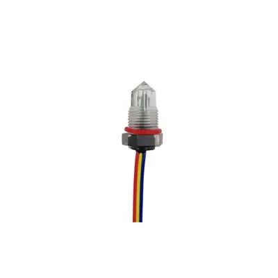
The diode is everywhere in the sensor world - the flyback diode on every relay output, the ESD diodes on every input, and the IR LED plus phototransistor at the heart of optical level sensors: The diode in the sensor world appears in five places. The relay outputs - the flyback diode across the relay coil: when the coil de-energizes, its inductance drives a spike that would kill the driver transistor, and the diode clamps it - the standard protection on every relay-driven sensor output. The inputs - ESD and TVS diodes: static discharge and line transients are clamped to the rails before they reach the electronics. The optical sensors - the IR LED and phototransistor pair: the LED emits the light and the phototransistor (a photodiode's cousin) detects it - the heart of TIR optical level sensors, where the light path changes with the liquid. The power rails - rectifier and reverse-polarity diodes: the supply is rectified and protected against reversed wiring. The indicators - the LED with its series resistor: the status light on every controller, which is why "the LED is lit" is the first check in troubleshooting. The reading: the diode is the sensor's silent infrastructure - it protects the drivers, clamps the inputs, lights the indicators, and senses the light. (The optical pair: How Optical Liquid Level Sensors Work; the relay protection: Why Flyback Diodes Are Required Across Relay Coils; the outputs: What Are the Different Types of Switches?.)
Troubleshooting
Shorted, Open, Leaky - and the Multimeter Test
The troubleshooting table (Featured Snippet):
| Symptom | What it means | The test |
|---|---|---|
| Shorted | The junction conducts both ways | Multimeter: low resistance in both directions |
| Open | The junction blocks both ways | Multimeter: no conduction in either direction |
| Leaky | Reverse current above spec | Multimeter diode test: significant reverse reading |
| No rectification | The output is half-wave or absent | Check for a reversed or blown diode |
| Overheating | Forward current or ambient too high | Check the load, the derating, and the heat path |
| Flyback failure | The driver transistor dies repeatedly | Test the flyback diode - it is the protection |
The troubleshooting table is the diode's service page - shorted, open, and leaky are the three failure modes, and the multimeter's diode test catches all three: The troubleshooting table for diodes covers the three failure modes. Shorted - the junction conducts both ways: the multimeter shows low resistance in both directions; the classic cause is an overcurrent or an avalanche beyond rating. Open - the junction blocks both ways: no conduction in either direction; the classic cause is a melted junction from sustained overload. Leaky - the reverse current above spec: the diode test shows a significant reverse reading; the classic cause is heat damage or age. No rectification - the output is half-wave or absent: check for a reversed diode (blocks instead of conducting) or a blown diode (open). Overheating - the forward current or ambient too high: check the load, the derating, and the heat path. Flyback failure - the driver transistor dies repeatedly: test the flyback diode - it is the protection, and when it fails open, the coil's spike kills the driver on the next de-energization. The test: the multimeter's diode mode applies a small forward voltage and reads the junction drop - about 0.6 V for silicon, 0.3 V for Schottky - and the reverse reading should be open (or "OL"). The rule: a diode is shorted, open, or leaky - and the multimeter tells you which in seconds. (The test discipline: Sensor Data Sheet: How to Read and Use One; the driver protection: Why Flyback Diodes Are Required Across Relay Coils; the reading: How to Read a Schematic.)
FAQ
Q1: What is a solid state diode in simple terms?
A solid state diode is an electronic one-way valve: it lets current flow in one direction and blocks it in the other. The heart is the PN junction - where N-type and P-type silicon meet, a carrier-free depletion region forms, and the applied voltage either narrows it (forward bias - conduction) or widens it (reverse bias - blocking).
Q2: What is the difference between a diode and a transistor?
A diode has two terminals (anode and cathode) and one junction - it conducts or blocks based on the applied voltage. A transistor has three terminals and two junctions - a small current or voltage at the base (or gate) controls a larger current between the other two terminals. The diode is the one-way valve; the transistor is the controlled valve.
Q3: What is a diode used for?
Rectification (AC to DC), protection (flyback diodes across relay coils, TVS clamps, reverse-polarity protection), voltage reference (Zener), light emission (LED), light detection (photodiode), and voltage-controlled tuning (varactor). Nearly every electronic circuit uses diodes in several of these roles.
Q4: Why do we put a diode across a relay coil?
The relay coil is an inductor. When its current is interrupted, the coil drives a voltage spike (V = L·di/dt) that can destroy the driver transistor. The flyback diode, connected in reverse across the coil, clamps the spike by conducting the stored energy around the coil - the driver is protected.
Q5: How do I test a diode with a multimeter?
Use the diode test mode: it applies a small forward voltage and reads the junction drop - about 0.6–0.7 V for silicon, 0.3 V for Schottky - in the forward direction, and open (OL) in reverse. A shorted diode reads low in both directions; an open diode reads OL in both.
The Bottom Line
A solid state diode is a two-terminal semiconductor device that allows current to flow in one direction only - the electronic one-way valve. The heart is the PN junction: N-type silicon carries free electrons, P-type carries holes, and where they meet, the depletion region forms - the carrier-free zone that blocks current. Forward bias narrows the depletion region until the junction conducts; reverse bias widens it and the diode blocks. The IV curve is the fingerprint: a steep forward turn-on after the threshold (0.6–0.7 V silicon, 0.3 V Schottky, 2–3 V LED), a flat reverse block with a small temperature-dependent leak, and a wall at the reverse breakdown - which the Zener exploits and the TVS rides. The family is the one-way valve in eight costumes: rectifier, Schottky, Zener, LED, photodiode, TVS, varactor, and signal diode. The famous circuits are the half-wave and full-bridge rectifier, the flyback diode across relay coils, the Zener shunt regulator, and the TVS clamp. The parameters - forward current, reverse voltage, recovery time, leakage, and power rating - are the safe operating contract, and the derating rule is the reliability rule. In the sensor world, the diode is the silent infrastructure: the flyback diode protects every relay output, the ESD and TVS diodes clamp every input, and the IR LED plus phototransistor pair senses the light at the heart of optical level sensors. The troubleshooting is shorted, open, or leaky - and the multimeter's diode test tells you which in seconds. The one-sentence rule: the diode is the simplest semiconductor - a one-way valve made of a junction - and nearly every electronic circuit, including every sensor, leans on it. (The flyback anchor: Why Flyback Diodes Are Required Across Relay Coils; the optical pair: How Optical Liquid Level Sensors Work; the solid-state family: What Are Solid State Relays (SSRs)?; the fundamentals: Gates vs Switches: A Conceptual Framework.)
Last updated: August 2026
Disclaimer: This article is an educational guide to solid state diodes, for general reference. The PN junction physics, IV curve characteristics, diode family types, circuits, parameters, and troubleshooting guidance reflect common engineering knowledge and vary by manufacturer, material, and device; always verify the specific diode's data sheet (forward voltage, reverse voltage, forward current, recovery time, leakage, power rating, temperature derating) with the manufacturer's documentation. Circuit design and testing must be performed by qualified personnel.