Sensor Data Sheet: How to Read and Use One
In this guide: What a sensor data sheet is and why it carries legal weight, the typical sections you will find, the key parameters (electrical, mechanical, environmental, output, accuracy, compliance) and what each one really means, how to read a data sheet for selection, a worked example using real verified sensor values, the common pitfalls that cause field failures, data sheet vs. manual vs. catalog, and the complete FAQ.
What Is a Sensor Data Sheet? - Quick Answer
A data sheet is the manufacturer's official specification document for a sensor - the binding reference for every electrical, mechanical, environmental, output, accuracy, and compliance number you must check before you buy or install. For sensors, the lines that decide success or failure are supply voltage, output type (NPN / PNP / 4–20 mA), operating temperature, ingress protection (IP), process connection, and accuracy. Reading the data sheet correctly is what prevents a sensor that "looks right" from failing in the field - wrong voltage, wrong polarity, wrong output logic, or an environment outside its rated range. Treat the data sheet as the contract; everything else is marketing.
What a Data Sheet Actually Is
Document, Not Advertisement
What it is and isn't:
| Aspect | Data Sheet | Catalog / Web Page |
|---|---|---|
| Author | Manufacturer engineering | Marketing |
| Weight | Specified, often warranted | Illustrative |
| Numbers | Guaranteed (within tolerance) | Typical / rounded |
| Use | Selection + acceptance | Discovery |
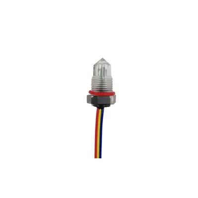
The contract, not the brochure: A data sheet is written by the manufacturer's engineering team and states the guaranteed performance of a specific part number - within stated tolerances and conditions. A catalog or web page is marketing: it shows typical or rounded numbers to help you discover the product. When you accept a shipment or design a system, the data sheet is the document you hold the supplier to. If a sensor does not meet its data sheet under the stated conditions, that is a non-conformance; if it merely looks different from the brochure photo, it is not. (Product context: OS2 Digital Optical Level Sensor.)
Typical Data Sheet Sections
The Map of the Document
Common sections:
| Section | What It Tells You |
|---|---|
| Description | What the device is, principle |
| Features | Headline capabilities |
| Specifications | The numbered table (the core) |
| Electrical | Supply, current, output, wiring |
| Mechanical | Dimensions, thread, material |
| Environmental | Temperature, pressure, IP |
| Performance | Accuracy, resolution, response |
| Compliance | Certifications, standards |
| Outline / DWG | Physical drawing, pinout |
Find the specifications table first: Almost everything you need lives in the "Specifications" (or "Electrical / Mechanical / Environmental Characteristics") table. The description and features tell you the category; the outline drawing tells you if it fits; but the specifications table is where the real acceptance numbers are. Learn to go straight there. (Drawing/pinout context: OS2 Digital - Implementation.)
Key Parameters, Explained
What the Numbers Mean
The parameters that decide fit:
| Parameter | Means | Watch For |
|---|---|---|
| Supply voltage | Operating range (e.g., 8–30 V) | Absolute max, not typical |
| Supply current | Draw (e.g., ~7.5 mA) | Power budget |
| Output type | NPN / PNP / 4–20 mA | Logic vs analog |
| Output load | Max (e.g., 1 A) | Don't overload |
| Operating temp | Rated range (e.g., −25~+80 °C) | Extended vs standard |
| Ingress (IP) | Dust/water (e.g., IP67) | Not submersion proof |
| Connection | M12×1, cable, thread | Match your harness |
| Accuracy | Error band (±%) | vs resolution |
| Response time | Reaction speed | <1 ms typical |
Read each line for its trap: Supply voltage is a range - 8–30 V means don't exceed 30 V and don't drop below 8 V; the absolute maximum is a destruction limit, not an operating setpoint. Output type decides your wiring: NPN (sinking) vs PNP (sourcing) vs analog 4–20 mA are not interchangeable. Operating temperature is the rated range; an "extended" range (e.g., −40~+125 °C) is a different rating than standard. IP67 means dust-tight and temporary immersion - it is not a depth rating. Accuracy is the error band; resolution is the smallest detectable step (they are not the same). Response time (<1 ms for solid-state optical) is how fast it reacts. (Output logic: Digital Output Level Sensor - OS2.)
How to Read It for Selection
From Need to Data Sheet
Match your requirement to the line:
| Your Need | Check The Line |
|---|---|
| Power available? | Supply voltage / current |
| Controller input? | Output type (NPN/PNP/4–20 mA) |
| Hot / cold? | Operating temperature |
| Wet / dusty? | Ingress protection (IP) |
| Tight space? | Outline drawing, thread |
| Precise? | Accuracy, resolution |
| Hazardous? | Compliance (ATEX/IECEx) |
Turn your spec into a checklist: Before opening the data sheet, write down what your system provides and requires: the supply voltage you have, the input type your controller expects (NPN/PNP/digital/analog), the temperature and ingress environment, the physical space and connection, the accuracy you need, and whether the area is hazardous. Then read the data sheet line by line against that checklist. A sensor passes only if every line is within your requirement - one out-of-range parameter is a reject. (Controller input: Arduino Interfacing with Water Level Sensor.)
Worked Example (Verified Values)
Reading a Real Optical Level Switch
Verified Optomax-class optical values:
| Line | Value | What It Tells You |
|---|---|---|
| Supply | 8–30 V DC | Wide, tolerant |
| Current | ~7.5 mA max | Low power |
| Output | NPN / PNP, ~1 A | Sinks/sources a load |
| Temp (std) | −25~+80 °C | Industrial range |
| Temp (ext) | −40~+125 °C | Extended option |
| Thread | M12×1 | Standard mount |
| Ingress | IP67–68 | Dust-tight, wet OK |
| LED | 850–950 nm IR | Invisible, modulated |
How to read it: An optical liquid-level switch rated 8–30 V DC runs from a 12 V or 24 V supply without a regulator. Its ~7.5 mA draw is trivial on a control loop. NPN/PNP, ~1 A means it can directly drive a relay, pump, or alarm (sinking or sourcing per your wiring). −25~+80 °C covers most plants; the extended −40~+125 °C option covers freezers or hot processes. M12×1 is a standard threaded mount. IP67–68 means it survives washdown and temporary immersion. The 850–950 nm IR LED is invisible and modulated to reject ambient light. Every line maps to a deployment decision - that is what "reading the data sheet" means. (Source family: OS4 Industrial Glass Optical Level Switch.)
Common Pitfalls
Where Data Sheets Bite
Mistakes that fail in the field:
| Pitfall | Consequence |
|---|---|
| NPN/PNP confusion | Wrong logic, no signal |
| Absolute vs operating temp | Cracked in cold/hot |
| IP misunderstood | Flooded sensor |
| Accuracy vs resolution | "Precise" but drifting |
| 4–20 mA live-zero ignored | Broken loop looks normal |
| Extended range assumed | Out of spec |
The six classic errors: (1) Wiring NPN where PNP is expected (or vice versa) - the sensor works but the controller sees nothing. (2) Treating the absolute-max temperature as the operating range - the part survives briefly then drifts or cracks. (3) Reading IP67 as "submersible" - it is temporary immersion, not depth-rated. (4) Confusing accuracy (error band) with resolution (smallest step) - high resolution does not mean high accuracy. (5) Forgetting 4–20 mA's live zero (4 mA = healthy loop, 0 mA = broken wire) - a dead loop can look like "empty." (6) Assuming the extended temperature range applies to the standard part. All six are data-sheet misreads, not component faults. (Live-zero: Capacitive Level Transmitters & Probes.)
Data Sheet vs. Manual vs. Catalog
Three Different Documents
Don't confuse them:
| Document | Purpose |
|---|---|
| Data sheet | Guaranteed specs of the part |
| Manual | Install, configure, troubleshoot |
| Catalog | Discover / compare range |
Use the right one at the right time: The data sheet is for selection and acceptance - the guaranteed numbers. The manual (or installation guide) is for wiring, configuration (e.g., teach-in, WebCal), and troubleshooting once you own it. The catalog is for discovering and comparing the range before you choose. Reading the manual to decide if a sensor fits (instead of the data sheet) leads to surprises; reading only the catalog leads to mismatched specs. Know which document answers which question. (Config example: EchoPod General Purpose Ultrasonic Level Sensor.)
Frequently Asked Questions
Q1: What is the most important line on a sensor data sheet?
For selection, it is the combination of supply voltage and output type, because those decide whether the sensor will even connect and communicate with your system. A sensor with the right principle but the wrong output (e.g., PNP where you need NPN, or analog 4–20 mA where you need a digital input) is unusable without extra hardware. After that, operating temperature and ingress protection decide whether it survives the environment. Check those four lines first; accuracy and response come after the sensor is physically viable.
Q2: What is the difference between NPN and PNP output?
NPN is a sinking output - when active, it pulls the line low (to ground); it expects a load connected to the positive supply and is common with MCU/Arduino-style pull-up inputs. PNP is a sourcing output - when active, it drives the line high; it is common with most PLC sink inputs. They are not interchangeable by wiring alone; you must match the sensor's output to the controller's input type (or add an interface). Many industrial sensors offer either NPN or PNP, and some configurable parts support both. (Deep dive: Digital Output Level Sensor - OS2.)
Q3: Does IP67 mean the sensor is waterproof?
Not exactly. IP67 means "dust-tight" and "protected against temporary immersion in water up to 1 m for up to 30 minutes." It is not a depth or continuous-submersion rating (that is closer to IP68, and even then only to a stated depth/time). A sensor rated IP67 survives splash, washdown, and brief immersion, but you should not assume it can sit submerged indefinitely. The data sheet's ingress line - and any depth footnote - is the authority.
Q4: What is the 4–20 mA "live zero" and why does it matter?
In a 4–20 mA loop, 4 mA represents the empty (or zero) condition and 20 mA the full condition; 0 mA means the loop is broken (wire cut, power lost, sensor fault). That "live zero" is deliberate: it lets the controller distinguish "reading empty" (4 mA, healthy) from "loop failed" (0 mA, fault). If you ignore it and treat 0 mA as "empty," a broken wire looks like a full-or-empty tank and you lose the fault alarm - a classic data-sheet misread with safety consequences. (Loop detail: Capacitive Level Transmitters & Probes.)
Q5: How do I know if a data sheet value applies to my exact part?
Check the part-number suffix and any option notes. Manufacturers often list a family range (e.g., standard −25~+80 °C and extended −40~+125 °C) where only one applies to the specific variant you are buying. The same is true for output type, thread, and tip material (plastic vs glass). The data sheet's "ordering information" or variant table maps the suffix to the exact values; the headline range is the family maximum, not necessarily your part. Confirm the suffix before you accept the shipment.
The Bottom Line
A sensor data sheet is the manufacturer's guaranteed specification - the contract you select and accept against - and the lines that decide success are supply voltage, output type (NPN/PNP/4–20 mA), operating temperature, ingress protection, connection, accuracy, and compliance. Read the specifications table first, map each line to your actual requirement (power, controller input, environment, space, precision, hazard area), and reject any sensor with even one out-of-range parameter. Watch the classic traps: NPN/PNP mismatch, absolute-vs-operating temperature, IP67 ≠ submersible, accuracy ≠ resolution, the 4–20 mA live zero, and assuming the extended range. Use the data sheet for selection and acceptance, the manual for installation and configuration, and the catalog only for discovery. The data sheet is the document you hold the supplier to - everything else is marketing.
Last updated: August 2026
Disclaimer: This guide explains how to read a sensor data sheet for educational purposes. Example values used (supply 8–30 V DC; ~7.5 mA; NPN/PNP output ~1 A; operating −25~+80 °C, extended −40~+125 °C; M12×1; IP67–68; IR LED 850–950 nm; 4–20 mA live-zero where 4 mA = empty/healthy and 0 mA = broken loop; NPN sinking / PNP sourcing) are drawn from verified datasheet-class values of the Optomax optical level switch family and the Flowline EchoPod ultrasonic transmitter family cited elsewhere in this sensor cluster, and are presented as illustrative examples only. Exact specifications, variant suffixes, certification scopes, and ratings vary by manufacturer and part number - always read the official data sheet for the specific part you intend to use, and verify against applicable standards (ATEX, IECEx, and local electrical/instrumentation codes) before selection or installation. This guide is not affiliated with or sponsored by any manufacturer.